Transparent Plastic Sheet & Film Inspection Automation

Book a call

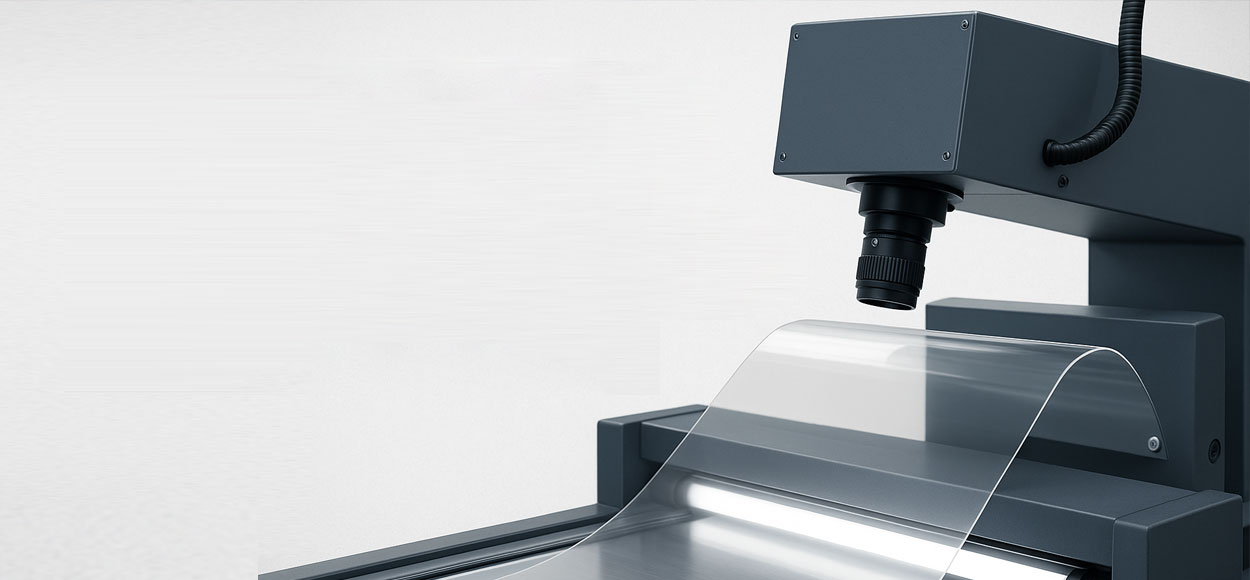
Compatible with all major plastic types

PET
PETG
PC
PMMA
PA
PP/PE
PVC
COP/COC

Transparent Plastic Inspection

Why transparent sheets/films are hard—and how we solve it

Common inspection pitfalls

Transparency

Defects disappear without the correct light path/background.

Low contrast

Gels, fish-eyes, inclusions, and pinholes often blend into the scene.

Specular glare & web flutter

Reflections and vibration cause false alarms and blur.

Thickness & birefringence variations

Brightness/strain patterns mimic defects.

Coatings & laminates

Add haze, streaks, and interface bubbles.

Intelgic approach

Transmission lighting matched to task

Collimated/telecentric backlight for pinholes, diffuse transmission for thickness mapping.

Surface lighting

Low-angle dark-field for scratches, coaxial/dome with polarization to suppress glare.

Polariscopy (optional)

For stress/birefringence visualization on PC/PMMA.

Web engineering

Encoder sync, anti-flutter rollers, vibration-tolerant exposures.

Live Vision AI

With thickness-aware background models and streak/periodicity filters to minimize false positives.

Technology

System Architecture

Imaging hardware

  • Line-scan cameras (2k–8k) for continuous web coverage
  • Telecentric lenses for metrology; high-NA macro for micro-defects
  • Liquid lens for rapid focus when switching thicknesses

Lighting geometry

  • Telecentric/collimated backlight: pinholes, edges, silhouette
  • Diffuse transmission panels: gels, thickness/uniformity maps
  • Coaxial/dome with polarization: coated surfaces, glare control

Controllers & Software

  • Industrial PCs with GPU acceleration
  • Live Vision AI with thickness-aware background models
  • Defect classifiers for all common plastic defects

Inspection strategies by station

A

Transmission (diffuse)

Global uniformity & inclusions; thickness proxy map

B

Transmission (telecentric)

Pinholes, edge/tear detection, silhouette metrology

C

Surface (low-angle dark-field)

Sleeks, micro-scratches, die lines

D

Coating QA (optional)

Coaxial/dome with polarization for AR/HC/adhesive coats

Performance & throughput

Detection capability

Pinholes

≥10–20 µm

Gels/specs

≥20–50 µm

Scratches

<10 µm

Web speed

Up to 80 m/min per lane (higher possible with reduced FOV and optimized optics)

Metrology

Width/edge stability & silhouette features; thickness uniformity as relative index

Quality Assurance

Defects We Detect

Material / extrusion

  • Gels, black/white specs, unmelt, contaminants, crystal haze
  • Fish-eyes, orientation streaks, splay, flow lines
  • Gauge/thickness non-uniformity (relative mapping)

Surface / mechanical

  • Micro-scratches/sleeks, scuffs, dents/dings
  • Die lines, chatter marks, orange peel
  • Wrinkles, fold lines, web creases

Coating / laminate

  • Haze increase, streaks, voids, wetting issues
  • Interface bubbles/seeds, delamination starts

Digital Quality Certificate (DQC)

Each roll/coil or cut sheet receives a comprehensive quality certificate with complete traceability.

  • Roll ID/lot, start-stop timestamps, recipe & software version
  • Defect map with coordinates, type, and size/severity
  • Summary KPIs (defects/m², pinhole counts, streak length, uniformity index)
  • PASS/FAIL logic with thresholds; operator/station traceability; secure share links

DQC #2023-06-4872

PASS

Roll ID

PET-23-4872

Thickness

0.125mm ±5%

Length

1,842m

Defects/m²

0.8

Defect Map Criticality: Low

Pinholes

2

Gels

3

Scratches

0

Industries

Typical Lines & Applications

Extrusion & calendaring

PC, PMMA, PET, PVC sheets

Blown/cast films

PET, PA, PP/PE, multilayer barrier

Coated/functional films

Hard-coat, AR/AG, adhesive (PSA), release liners

Laminates

Displays, glazing, solar, packaging

Details

Technical Specifications

Cameras

  • 2k–8k line-scan; optional 12–45 MP area-scan
  • HDR/global shutter

Optics

  • Telecentric 0.3–1.0×
  • Macro up to 5×
  • Liquid lens autofocus

Lighting

  • Diffuse & telecentric/collimated backlights
  • Low-angle dark-field bars; coaxial/dome
  • Polarization; optional UV/NIR; polariscopy

Interfaces

  • OPC-UA, Modbus/TCP, Ethernet/IP, REST
  • Barcode/RFID; slitter/rewinder IO

Frequently Asked Questions

Yes. Diffuse transmission creates calibrated intensity maps; AI models subtract expected thickness gradients to highlight true inclusions and gels.

Encoder‑synchronized exposure, short strobe pulses, anti‑flutter rollers, and vibration‑tolerant processing maintain sharpness.

Yes. The web map includes lane coordinates so slitters/rewinders can avoid defect bands or trigger auto‑markers.

Coaxial/dome with polarization elevates coating pinholes, haze, and streaks; we can also monitor uniformity trends.

We provide relative haze/clarity indices inline; for absolute conformance (e.g., ASTM methods), we can integrate with off‑line instruments and link results to the DQC.

Say hello to Intelgic

contact intelgic
Book a call

©2025 Intelgic Inc. All Rights Reserved.