Sunglass Lens Inspection Automation

(Polarized, Mirrored & Tinted)

Book a call

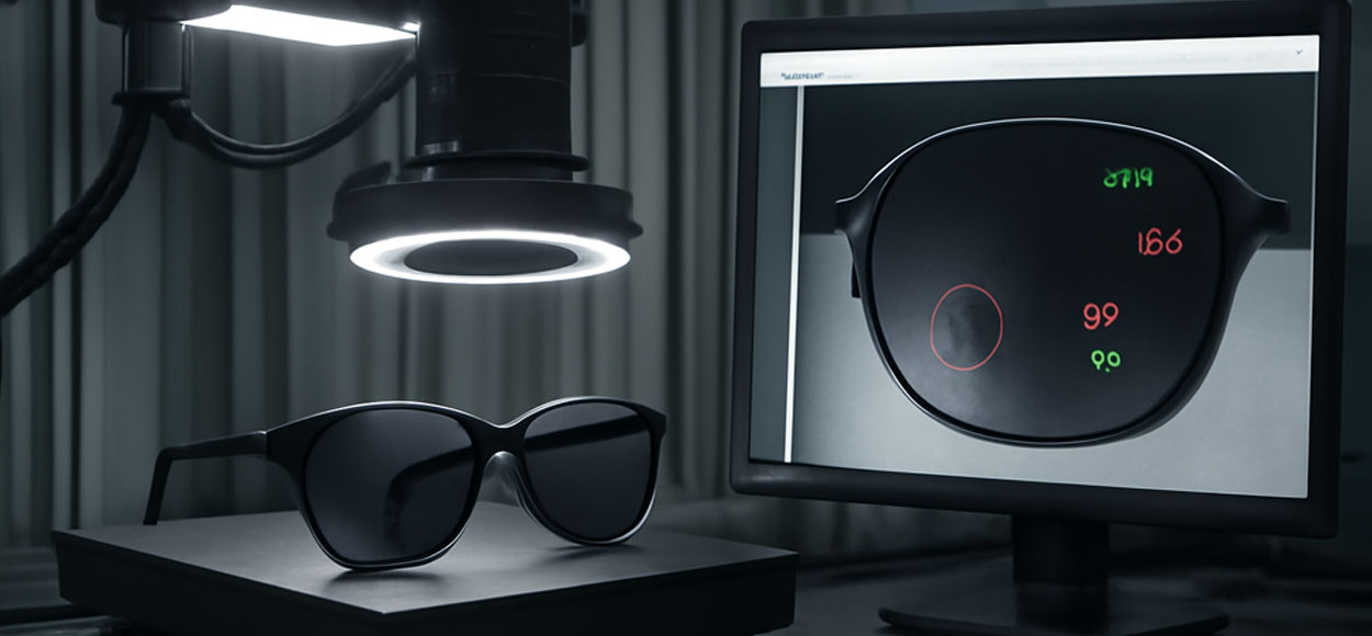
Style meets certified safety. Intelgic automates visual, cosmetic, and optical inspection of sunglass lenses—polycarbonate, CR‑39, high‑index, glass, TAC laminated, and film‑based polarizers—across surfacing, tinting, coating, edging, and final QC. Our turnkey system pairs precision optics, application‑specific lighting geometry, polarization metrology, and Live Vision AI to detect micro‑defects, verify tint and polarization, measure geometry, and issue a Digital Quality Certificate (DQC) for every PASS lens or matched pair.

Why sunglass lenses are uniquely challenging

Sunglass lenses are transparent, curved, and often coated or laminated. Typical hurdles include:

Transparency + High Gloss

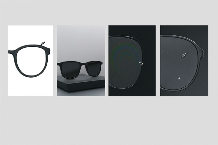
Glare hides sleeks, hairline scratches, pinholes, and stains.

Polarizing Films

Demand axis accuracy and high extinction; mis-alignment causes visual strain.

Tint & Gradient Uniformity

Uneven dyeing or mirrored layers create blotches/hot-spots.

Mirror/IR/AR Coatings

Specular reflections confuse classic vision tools.

Curvature and Decentration

Refraction shifts apparent defect position; edge chips affect assembly.

Intelgic's Solution

Task‑matched lighting

  • Telecentric/collimated backlight for silhouette, edge chips, center/edge thickness and wedge.
  • Coaxial bright‑field for coating pinholes, haze, water spots, rainbow.
  • Low‑angle dark‑field for sleeks, micro‑scratches, digs.
  • Cross‑polarization to suppress glare and isolate coating defects on mirrored/AR surfaces.

Polarization metrology

  • Automated polarization axis detection using a programmable polarizer/analyzer pair with rotation sweep and intensity fit.
  • Extinction/efficiency estimation and left–right axis match verification for pairs.

Spectral/transmission tests (optional modules)

  • Controlled UV/visible source + sensor to estimate luminous transmittance and UV cut; gradient/tint uniformity maps.
  • Custom machine vision design for each SKU: we tune lighting geometry, optics, and motion to material, base curve, tint/coat stack, and takt time.
  • Live Vision AI trained on sunglass datasets—reflection‑aware, thickness‑aware, and pair‑aware—to reduce false positives and ensure pair matching.
  • Microscopic capability: with appropriate optics, Intelgic detects <10 µm surface scratches and ≥20–30 µmcoating pinholes on glossy lenses (application‑dependent).

What We Inspect

Surface & coatings

  • Hairline scratches, sleeks, scuffs, digs/pits
  • Coating defects: mirror/IR, AR, hard‑coat pinholes, streaks, haze, delamination, water spots
  • Contamination: fingerprints, polish residue, dust nibs

Polarization & tint

  • Polarization axis and efficiency/extinction; axis match for left–right pair
  • Tint/gradient uniformity and ΔE color variance maps
  • UV/visible transmittance estimates (with stimulus module); optional photochromic response tests

Edges & geometry

  • Bevel chips, shelling, sharp edges; diameter, optical center vs. marks, center/edge thickness, wedge
  • Decentration inference via marks and optical center analysis

Layout & markings

  • Brand logos, laser/micro‑marks, ink stamps; OCR/OCV; placement tolerances

Typical stations & use cases

Post‑tinting

Gradient and uniformity maps; early tint defects before coating

Post-Coating

(mirror/AR/hard): glare‑suppressed pinhole/haze detection

Polarization station

Axis/efficiency measurement and left–right pair matching

Post‑edging/finishing

Bevel chips, diameter, wedge, mark verification

Final QC & packaging

Full audit -> DQC with optical and cosmetic results

System Architecture

Imaging hardware

  • Cameras: High‑resolution area‑scan (12–45 MP) with HDR for high‑gloss scenes
  • Optics: Telecentric lenses for metrology; high‑NA macro for micro‑defects; liquid lens for rapid autofocus across curvature
  • Lighting geometry
    • Telecentric/collimated backlight for geometry & silhouette
    • Coaxial bright‑field for coating defects
    • Low‑angle dark‑field for sleeks/scratches
    • Polarization kits (cross‑pol and rotating analyzer)
    • Uniform dome for color/tint cosmetics and gradient mapping
  • Polarization unit (automated): motorized polarizer/analyzer with angular encoder; reference calibration lens set
  • Spectral/UV module (optional): stabilized UV/visible source and calibrated sensor for transmittance estimates
  • Motion & fixturing: Rotary/flip module for both faces; auto‑centering nests; barcode/RFID reader
  • Controllers: Industrial PCs with GPU acceleration; synchronized strobes; PLC/robot IO

Imaging hardware

  • Recipe‑based inspection by material, tint, coating, and base curve
  • Reflection‑aware segmentation; pair‑aware comparison for left–right matching
  • Metrology: diameter, CT/ET, wedge, optical center vs. marks; logo presence/position
  • Polarization analysis: axis (deg), relative extinction/efficiency; pass/fail to spec band
  • Tint/UV analysis: uniformity maps, ΔE statistics, UV cut estimate
  • Real‑time PASS/FAIL with reason codes; rework routing and reject diverter control

Integration layer

  • PLC/robot, MES/ERP via OPC‑UA, Modbus/TCP, Ethernet/IP, REST APIs
  • Label/laser marker integration for serialized IDs; data exchange with coaters and edgers

Pair‑matching analytics

Ensure customers receive perfectly matched lenses:

  • Axis delta (L‑R) report with tolerance bands
  • Tint ΔE match and gradient profile overlay
  • Geometry match: diameter, CT/ET, wedge comparison
  • One‑click pair approval and DQC bundle for each boxed set

Performance & throughput (typical)

  • Defect sensitivity: scratches/digs <10 µm; coating pinholes ≥20–30 µm (setup‑dependent)
  • Polarization axis resolution: better than ±0.5–1.0° (fixture‑dependent)
  • Tint uniformity: ΔE maps and gradient slope; UV cut estimate via stimulus module
  • Throughput: 600–1,800 lenses/hour (manual load cell); 10–30 lenses/min with automated rotary/flip
  • Performance varies with material, coatings, base curve, and acceptance criteria. Intelgic tunes optics, lighting, motion, and AI to your targets.

Digital Quality Certificate (DQC)

Each PASS lens or pair receives a DQC that includes:

  • Lens ID/pair ID, job, timestamp, recipe & software version
  • Annotated defect snapshots and measurement values (axis, ΔE, CT/ET, wedge)
  • PASS/FAIL logic with thresholds; operator/station traceability
  • Optional attachments: transmittance curves or photochromic response plots

Dashboard & KPIs

  • Yield by shift/material/tint/coat
  • Defect Pareto (coating vs. surface vs. edge vs. layout)
  • Pair‑match rates (axis, tint, geometry)
  • FP/FN trends, recipe drift, station utilization
  • Exports (CSV/PDF) and REST APIs for BI/QMS

Deployment options

  • On‑premises for real‑time control and data residency
  • Cloud or hybrid for centralized DQC, cross‑plant benchmarking, and model fleet updates
  • Mobile app for field returns analysis and supplier audits

Safety & compliance

  • Light guards, interlocks, E‑stops; anti‑scratch handling fixtures
  • Audit trails, role‑based access; e‑signatures (optional)
  • Documentation support for eyewear QMS; optional links to standards testing (performed off‑line) via data attachments

Implementation process

  • Discovery & samples → materials, tint/coat stack, defect taxonomy, optical tolerances, throughput
  • Feasibility lab → optics/lighting trials (coaxial, dark‑field, backlight), polarization & tint tests
  • Pilot cell → line integration and KPI validation
  • Deployment → installation, commissioning, operator training
  • Scale & support → multi‑line rollout, remote monitoring, SLA

Technical specifications (typical)

  • Cameras: 12–45 MP area; HDR/global shutter
  • Optics: telecentric 0.3–1.0×; macro up to 5×; liquid lens autofocus
  • Lighting: telecentric/collimated backlights; coaxial bright‑field; low‑angle dark‑field; cross‑polarized setups; uniform dome
  • Polarization: motorized polarizer/analyzer; angular encoder; reference lens kit
  • Spectral/UV: stabilized UV/visible source & sensor (optional)
  • Motion: rotary/flip; quick‑change nests; barcode/RFID
  • Interfaces: OPC‑UA, Modbus/TCP, Ethernet/IP, REST

Frequently Asked Questions

Yes. Cross‑polarized coaxial imaging isolates coating glare, while a rotating analyzer measures axis and extinction through the mirror stack.

Uniform dome illumination and calibrated colorimetry generate ΔE maps and gradient slope profiles for pass/fail decisions.

We estimate UV blocking with a controlled UV source/sensor module and record it in the DQC. For formal certification to specific standards, we can attach results from your off‑line instruments.

Yes. The pair‑matching module compares axis, tint ΔE, and geometry (diameter, CT/ET, wedge) and blocks packaging if out of tolerance.

We can run stimulus‑based darkening/clearing tests and log kinetics curves alongside standard cosmetic/geometry checks.

Say hello to Intelgic

contact intelgic
Book a call

©2025 Intelgic Inc. All Rights Reserved.