A practical, engineering-focused guide
Modern manufacturing increasingly deals with parts that have multiple functional surfaces, undercuts, curves, holes, chamfers, grooves, embossed features, and mixed finishes. Inspecting such parts using a single camera or a flat, top-down view is not sufficient. This is where multi-surface vision inspection systems—combining multiple cameras, engineered lighting, controlled environments, and automated part handling—become essential.
Why multi-surface inspection is fundamentally different
Unlike flat or single-face components, multi-surface parts present three major challeng
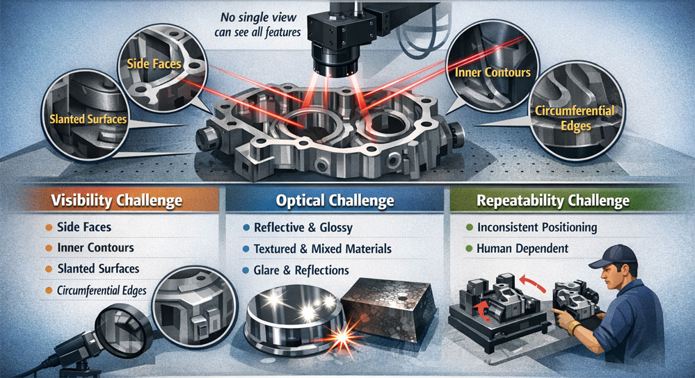
Visibility challenge
No single viewpoint can see all features
Critical defects may exist on:
- Side faces
- Inner contours
- Slanted or angled surfaces
- Circumferential edges
Optical challenge
Surfaces may be:
- Highly reflective (polished metal, chrome, coated parts)
- Semi-gloss or textured
- Mixed materials on the same part
Reflections, glare, and hotspots can easily hide defects
Repeatability challenge
- Inconsistent orientation leads to measurement errors
- Human-dependent positioning makes results non-repeatable
For these reasons, imaging process design—not just camera selection—is the most critical aspect of inspection automation.
Imaging all surfaces: multi-camera inspection architecture
Why multiple cameras are required
Multi-surface inspection relies on distributed viewpoints, each optimized for a specific surface or feature.
Typical configurations include:
- Top camera: overall geometry, top features, hole patterns
- Side cameras (2–4): vertical walls, grooves, embossing, side defects
- Angled cameras: chamfers, slanted surfaces, edge conditions
- Bottom or tilted cameras (optional): underside or recessed features
Each camera:
- Covers a well-defined field of view
- Has dedicated lighting optimized for that surface
- Is synchronized with part position and motion
This approach ensures full surface coverage without blind zones.
Lighting design: the backbone of accurate inspection
Why lighting matters more than cameras
For complex parts, lighting quality defines image quality more than camera resolution. Incorrect lighting will:
- Wash out fine defects
- Create false positives from reflections
- Hide scratches, dents, or surface deformation
Lighting for reflective and shiny surfaces
For shiny or reflective parts:
- Light intensity must be finely controlled
- Direct lighting often creates glare and hotspots
- Diffuse or indirect illumination is preferred
Common strategies:
- Dome or diffused lights for uniform illumination
- Low-angle (dark-field) lights to highlight surface scratches
- Cross-polarized lighting to suppress specular reflections
- Multiple light angles for the same surface
Multiple images of the same surface: when one image is not enough
Why multiple images are required
In many real-world cases, a single image cannot reveal all defect types.
Especially for reflective parts:
- Some defects are visible only at specific illumination angles
- Shallow dents or waviness appear only under grazing light
- Coating non-uniformity may require soft illumination
Practical implementation
The system captures:
- Multiple images of the same surface
With:
- Different light angles
- Different intensities
- Sequential illumination
These images are then:
- Independently analyzed
- Or logically combined by the inspection software to improve confidence
This method dramatically reduces false negatives, especially on polished or coated components.
Controlled inspection environment: eliminating ambient light effects
Why ambient light is a problem
Uncontrolled factory lighting introduces:
- Color variation
- Shadows and reflections
- Time-of-day inconsistencies
- Operator-dependent variability
This is especially damaging when:
- Inspecting color, texture, or surface finish
- Measuring dimensional features visually
Enclosure-based inspection approach
To ensure consistent inspection:
- The vision system is placed inside an enclosed inspection chamber
- Ambient light is completely blocked
- Only calibrated inspection lighting is used
Benefits:
- Stable imaging conditions
- Repeatable inspection results
- Easier AI model training and tuning
- Higher measurement accuracy
Automation for part movement and orientation
Why automation is necessary
Manual part loading introduces:
- Orientation errors
- Position variance
- Lower throughput
- Operator fatigue
For complex geometry parts, automated handling is essential.
Common automation methods
Depending on part size and shape:
- Linear actuators to move parts into and out of inspection zone
- Rotary stages to expose all circumferential surfaces
- X-Y-Z motion systems for precise repositioning
- Conveyors for inline inspection
- Robotic arms for flexible part manipulation
Automation ensures:
- Each part is inspected in a known, repeatable pose
- Camera triggers and lighting are synchronized perfectly
- High-speed and high-accuracy inspection
Inspection process flow (end-to-end)
- Part arrives at inspection station
- Automated system positions part inside enclosure
- Cameras and lights trigger in predefined sequence
- Multiple images are captured for different surfaces
- Software aligns and processes each image
- AI models detect defects and deviations
- Results are consolidated into pass/fail decision
- Part exits inspection area automatically
- Inspection data and images are stored for traceability
What defects can be detected on multi-surface parts
Using this approach, systems can reliably detect:
- Surface scratches, dents, and pits
- Cracks and fractures
- Coating and plating defects
- Color and finish inconsistency
- Missing or deformed features
- Incorrect geometry or orientation
- Assembly-related visual errors
- Tool marks and machining defects
Benefits of multi-surface vision inspection
Operational benefits
- 100% inspection coverage
- High repeatability and objectivity
- Reduced manual inspection dependency
- Faster inspection cycles
Quality benefits
- Early defect detection
- Reduced customer complaints
- Strong traceability and audit trails
- Consistent quality across shifts and plants
Engineering benefits
- Scalable architecture for future part variants
- Ability to add cameras or lighting as complexity increases
- Continuous improvement through data and AI feedback
Inspecting parts with multiple surfaces and complex geometry is not a camera problem—it is an imaging process and system design problem. By combining:
- Multi-camera setups
- Engineered lighting with fine intensity and angle control
- Multiple images per surface
- Controlled inspection environments
- Automated part movement
Manufacturers can achieve reliable, high-accuracy visual inspection even for the most challenging components.