Why 2D Counting Fails When Objects Touch
When objects are packed tightly:
- Edges disappear: The gap line between two objects may be invisible
- Shadows merge: Any shadow-based segmentation collapses into one region
- Same color/material: Two adjacent parts look identical
- Reflections/glare: Metallic or glossy surfaces wash out boundaries
- Random orientation: Parts overlap or rotate, making rules brittle
So the failure mode is simple: two parts become one connected component in the image.
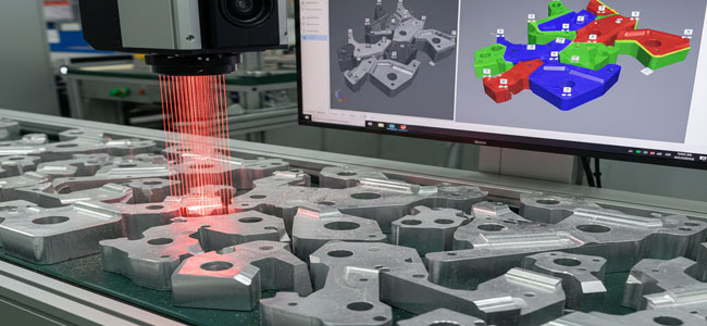
What a laser profiler camera measures
A laser profiler camera projects a laser line across the conveyor or tray and uses triangulation to measure the height (Z) at many points along that line. As parts move (or as a scanner moves), the system builds a 3D height map (also called a point cloud or depth image).
That gives Intelgic something incredibly useful:
Even if two parts touch in X–Y, there is often a height step, a valley, a ridge, or a curvature change at the contact boundary.
That boundary becomes measurable in Z, so we can separate parts using geometry, not only appearance.
Think of it like reading a “topographic map” of the pile.
Typical Intelgic solution architecture
A robust counting cell generally includes:
- Laser profiler camera (2D profile per frame) or scanning 3D sensor
- Stable mounting & mechanical reference (rigid frame, vibration isolation)
- Encoder / trigger synced to conveyor motion (for consistent 3D reconstruction)
- GPU/industrial PC for real-time processing
Live Vision AI software modules:
- Height map generation
- Segmentation & separation logic
- AI-based refinement (optional)
- Counting + reporting + PLC integration
Key principle:
If the conveyor speed varies, Intelgic syncs acquisition using encoder-based triggering, so the profile spacing stays constant. This is crucial for accurate 3D.
Step-by-step: How Intelgic counts “stuck” objects using 3D
Step 1 — Build a stable 3D height map
From each laser line profile:
- Convert profile pixels → real-world coordinates (X, Z)
- Use conveyor motion to accumulate profiles into a full surface model (X–Y–Z)
Output formats:
- Depth/height image (Z per pixel)
- Point cloud
- Range map + intensity map (many profilers also output intensity of reflection)
Step 2 — Remove background and flatten the reference plane
Most setups have a known reference plane (conveyor belt, tray, table). Intelgic:
- Fits a plane to background points
- Subtracts it to normalize Z
- Filters noise/outliers (median + bilateral/edge-preserving filters)
Result: parts stand out as “hills” above a flat ground.
Step 3 — Find candidate part regions using Z-thresholding
Instead of intensity thresholding (2D), we do:
part_mask = Z > Z_min
Where Z_min is chosen so small belt texture doesn’t appear, but parts do.
This step is extremely stable even under lighting variation.
Step 4 — Separate touching parts using geometric cues
This is where laser profiling shines. Intelgic typically uses a combination of:
Height-gradient boundaries (slope changes)
Compute:
- Gradient magnitude (∂Z/∂x, ∂Z/∂y)
- High gradient zones often indicate edges or contact boundaries
If two parts touch, the boundary often has:
- A small ridge line
- A valley line or a sudden change in curvature
Curvature / surface “shape signature”
Compute second derivatives or curvature-like features:
- Helpful when edges are rounded and gradient alone is weak
Watershed segmentation on height map (classic and effective)
A very common, robust method:
- Treat the height map like terrain
- Detect peaks
“Flood” downward to separate basins This often splits touching objects cleanly when there are multiple local maxima.
Distance transform on Z-mask + marker-based split
If the parts are similar sized:
- Convert part mask → distance transform
- Find local maxima as “markers”
- Apply marker-based watershed
This is a standard approach but works far better on Z-based masks than 2D masks.
Step 5 — Validate objects using 3D metrology (quality gates)
Once segmented, Intelgic applies physical constraints to avoid false splits:
Area range (mm²)
Height range (mm)
Volume estimate (integral of Z over region)
Length/width (from bounding box or PCA)
3D shape match (template in height space)
These gates ensure the system doesn’t mistakenly split one object into two.
Step 6 — Count + track across frames (if parts move)
For moving belts, a single object might appear across multiple profiles. Intelgic uses tracking logic:
- Track centroids in conveyor direction
- Assign IDs
- Count when an object crosses a virtual line (like a “counting gate”)
This avoids double-counting and handles partial visibility.
Where AI fits (and where it doesn’t need to)
A big advantage of laser profiling is that you can solve many “touching object” problems without heavy AI, using geometry.
Intelgic typically uses AI when:
- Shapes vary a lot
- There are overlaps/partial occlusions
- Some objects are damaged/deformed
- The boundary signature is inconsistent
In such cases Intelgic may:
- Use a lightweight segmentation model trained on height maps (Z images)
- Or use hybrid logic: 3D segmentation gives candidates and AI refines split/merge decisions
Result: high accuracy without overfitting to lighting conditions.
Real-world examples where laser profiling is the right choice
Laser profiler counting excels when objects are:
Challenging Materials
- Same color / low contrast (2D fails)
- Reflective metal parts
- Black rubber / textured surfaces
- Transparent/translucent items
Common Industrial Use Cases
- Fasteners, clips, bushings, small castings
- Extrusion cut pieces
- Food items where 2D texture varies
- Pharmaceutical packaging components
Engineering Considerations for Reliability
Conveyor Speed Variation
- Use encoder triggering so the point spacing stays consistent
- If encoder isn't available, Intelgic can estimate speed, but encoder is preferred
Vibration and Mounting
- Rigid frame and isolation are critical; tiny vibrations look like height noise.
Surface Reflectivity
- Proper sensor selection (laser wavelength/power)
- Angle tuning to reduce specular reflection
- Sometimes add a second view if needed
Object overlap (true stacking)
If objects are physically stacked (one on top of another), counting becomes a 3D occlusion problem. Laser profiling can still help, but solutions may require:
- Multi-pass scan
- Multiple sensors or more advanced AI + volumetric reasoning
Performance metrics Intelgic reports to clients
A production-grade system should be measured on:
- Count accuracy (%)
- False split rate (one part becomes two)
- False merge rate (two parts become one)
- Throughput (parts/min or belt speed)
- Latency (ms)
- Repeatability under lighting/shift changes
Intelgic typically also provides:
- Image/height-map evidence per count event
- Batch-wise and shift-wise analytics dashboards
- PLC handshakes and reject logic integration
Summary: why this approach works for “closely stuck” objects
Intelgic’s core advantage in this counting problem is the shift from 2D appearance to 3D geometry:
"Touching parts look merged in 2D,
but in 3D they usually reveal boundaries through height/shape changes."
With encoder-sync + robust segmentation + physical validation gates, the system becomes stable, explainable, and production-ready.