How a 3D Laser Profiler Measures Automobile Part Dimensions
Published on: Jan 06, 2026

Written by:Content team, Intelgic
Automotive manufacturing demands tight dimensional control—often down to a few tenths of a millimeter, and in many cases far tighter—because small deviations can cause assembly issues, NVH problems, leakage, premature wear, or safety risks. A 3D laser profiler (also called a laser line profiler or 3D profile sensor) is one of the most practical tools for fast, non-contact dimensional measurement on production lines. It captures high-density 3D geometry and converts it into measurable features like heights, widths, gaps, flushness, hole depth, step, angle, radius, and profile shape.
Below is an end-to-end explanation of how it works and how it’s applied in real automotive measurement tasks.
What a 3D Laser Profiler Is (and why it’s different)
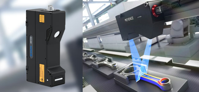
A 3D laser profiler typically projects a laser line onto a surface and views that line with a camera at a known angle. As the part (or the sensor) moves, the system captures many 2D “slices” of the surface and reconstructs a 3D height map or point cloud.
Key difference vs. a normal camera:
A 2D camera measures in pixels and needs careful calibration, lighting control, and feature contrast.
A 3D profiler directly measures surface height (Z) using physics and geometry, not appearance.
This makes it extremely reliable for:
- Metallic parts with changing textures,
- Black/reflective surfaces (with the right configuration),
- Measurements where edge contrast is poor,
- Dimensional checks under varying ambient lighting.
Core working principle: Laser triangulation (in simple terms)
Most 3D profilers in automotive inspection use laser triangulation:
- A laser projects a thin line onto the part.
- A camera views the line from an offset angle.
- If the surface height changes, the laser line appears shifted in the camera image.
- Because the laser/camera angles and geometry are known, the system converts that shift into real-world height values.
So each captured frame yields a 3D profile (a cross-sectional slice):
Each scan yields a 3D profile (cross-sectional slice):
- X axis: Along the laser line
- Z axis: Height (distance)
- Y axis: Built over time as the part moves
Result: a complete 3D reconstruction suitable for dimensional measurements.
What data you get: Profile → Point Cloud → Height Map
A) Raw profile data (fastest)
Each scan returns a single cross-section.
- Step height
- Groove depth
- Bead height
- Flange angle
- Gap/flush along a line
B) Point cloud (full 3D geometry)
Many profiles combined.
- Hole position and tilt analysis
- Surface flatness
- Volumetric checks
- Complex contours (gear tooth profile, cast shapes)
C) Height map (2.5D)
A grid of Z values (like a topographic map).
- Thresholding by height
- Plane fitting
- Region-based measurement
- Quick pass/fail rules
Typical automotive dimensions measured with a 3D laser profiler
Step height and flushness
Used in body-in-white, closure panels, trims:
- Measure step between two surfaces
- Measure flushness across edges
- Compare against tolerance limits
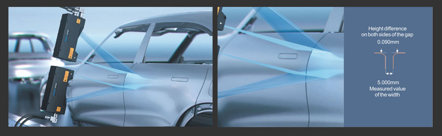
Example: door outer panel flushness to adjacent panel (±0.5 mm typical, sometimes tighter).
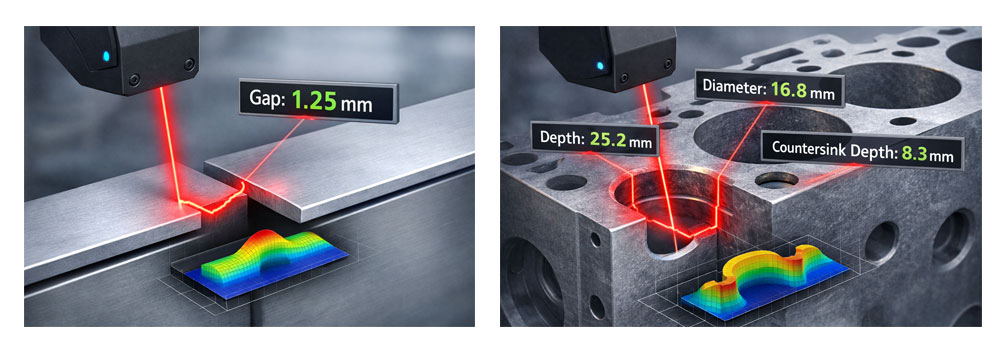
Gap Measurement
Measure the distance between edges:
- Seam gaps
- Assembly clearances
- Gasket seating gaps
3D helps because edges may be poorly contrasted in 2D images.
Hole Geometry and Depth
Used in engine blocks, castings, brackets:
- Hole depth
- Countersink/counterbore depth
- Hole diameter (derived from cross-section)
- Chamfer presence
- Tilt or eccentricity (with multi-line scans or controlled motion)
Bead and Sealant Measurement
Used in battery packs, windshields, sealing stations:
- Bead height
- Bead width
- Bead continuity
- Bead volume estimate
This is one of the most valuable use cases because 2D cameras can't reliably measure bead height.
Weld Bead and Joint Profiling
Used in chassis, BIW:
- Weld bead height/width
- Undercut detection
- Burn-through indicators (geometry anomalies)
Surface Flatness, Warpage, and Planarity
Used for machined faces, gasket surfaces, cast sealing faces:
- Fit a reference plane
- Compute deviations across regions
- Report max/min/average deviation
- Detect warp/bow/twist
Profile Shape Verification
Used for extrusions, stamped profiles, rubber seals:
- Compare measured cross-section to CAD reference profile
- Compute deviation envelope
- Detect dents, bends, improper forming
Measurement Workflow on a Production Line
A well-designed 3D laser inspection system typically follows this flow:
1 Part Presence and Triggering
- Photoelectric sensor / encoder trigger
- PLC synchronization (important!)
- Decide scan start/stop window
2 Data Acquisition (Profiles)
Capture rate depends on:
- Line speed
- Required resolution
- Feature size
3 Calibration & Conversion to Real Units
Sensor performs internal calibration, but system-level calibration may include:
- Coordinate alignment to part datum
- Scaling verification
- Transformation to a "part coordinate system"
4 ROI Selection (Measure Only What Matters)
- Define measurement zones (regions or scan lines)
- Ignore irrelevant geometry to keep cycle time low
5 Feature Extraction Algorithms
Common algorithms used in dimensional measurement:
- Plane fitting: find reference surface, compute deviations
- Edge detection in 3D: find sharp height transitions
- Line/curve fitting: measure radius, angle, slope
- Peak/valley detection: grooves, beads, steps
- Cross-section comparison to template/CAD: profile deviation
- 3D registration: align scan to nominal model (when needed)
6 Tolerance Check and Decision
- Compare each dimension to acceptance limits
- Output pass/fail + measured values
- Send results to PLC/MES/SCADA
7 Traceability and Reporting
Store:
- Measured values
- Timestamp
- Part ID (via barcode/OCR/RFID)
- 3D snapshot (compressed height map)
- Alarms and trends
Resolution, Accuracy, and What Affects Performance
When people say "resolution," they often mix three different things:
A) X Resolution (along laser line)
- Determined by sensor optics and camera pixels
- Often tens of microns to sub-mm
B) Y Resolution (scan direction)
- Determined by profile capture rate (Hz)
- Conveyor/part speed
- Encoder usage
C) Z Resolution (height)
- Determined by triangulation geometry and sensor quality
- Often micron-level repeatability in controlled conditions
Major Factors That Affect Measurement Quality
Surface reflectivity (shiny machined metal vs. matte cast)
Part vibration during scan
Poor synchronization with encoder
Temperature drift (mounts and fixtures expand)
Misalignment of part datum (inconsistent placement)
Contamination (oil film, coolant, dust, chips)
Integration Choices: Moving Part vs. Moving Sensor
A Conveyor Scanning (Part Moves)
Most common for production lines:
- Use an encoder tied to conveyor speed for uniform Y spacing
- Simple mechanical integration
- Best for high-volume, consistent parts
B Sensor Mounted on Motion System (Sensor Moves)
Useful for:
- Large parts (engine blocks, doors)
- Multiple measurement locations
- Controlled scan path for high accuracy
Requirements: Rigid mechanics (gantry/robot) and repeatable positioning
C Robot + Profiler (3D "Inspection Robot")
Flexible for varying SKUs but harder to guarantee metrology-grade accuracy unless:
- Robot is calibrated carefully
- Scan path and standoff are controlled
- Registration routines are used
Real Example Measurements
Example 1: Engine block hole depth + positional verification
- Move profiler over hole area
- Scan across the hole
- Detect hole edges (3D edge points)
- Fit circle/ellipse to edge points → center position
- Find bottom surface points → compute depth
- Output: depth, diameter estimate, center offset from datum
Example 2: Battery pack seal bead inspection
- Scan bead path continuously
- Extract bead cross-section each profile
- Measure height and width per profile
- Flag missing bead if height drops below threshold over a length
Example 3: Weld bead profile check
- Scan across weld
- Detect bead peak and toe points
- Measure bead height, width, and undercut depth
- Trend results to detect tool wear or process drift
Best Practices for Reliable Dimensional Measurement
1 Use Encoders for Moving Conveyor Scans
Critical for maintaining measurement accuracy when parts are moving. Encoders provide precise synchronization between part movement and scan timing.
2 Secure Your Datum References
Mechanical fixtures are just as important as the sensor itself. Ensure consistent part placement with reliable locators and clamps.
3 Optimize Measurement Regions
For tight cycle times, measure multiple small regions of interest rather than scanning entire parts. Focus only on critical features.
4 Build Golden References
Store profiles of known good parts and compare production parts statistically. This helps identify deviations before they become failures.
5 Add Process Analytics
Dimensional trends can predict tool wear, die drift, or clamp issues earlier than failures occur. Track measurements over time.
6 Optimize for Surface Types
Choose appropriate laser wavelength, power, and filters based on surface characteristics (shiny, dark, or oily parts).
Where 3D laser profilers outperform 2D and where they don’t
They outperform 2D when:
- Height/step/gap is the key measurement
- Edge contrast is unreliable for 2D
- Surface texture changes frequently
- Robust measurements under varying lighting are needed
They may not be ideal when:
- You need full 3D all-around geometry without moving the part (consider structured light or CT)
- Features are deep cavities not visible to the laser line from the chosen angle
- Very shiny mirror-like surfaces cause saturation (can be solved with proper sensor selection + polarization/filtering, but not always)
Intelgic’s End-to-End 3D Laser Profiling Measurement Solutions for Automotive Manufacturing
Intelgic delivers comprehensive, production-ready 3D laser profiling measurement solutions tailored to the exact dimensional and process requirements of automotive manufacturers. Rather than offering isolated components, Intelgic engineers and deploys fully integrated measurement systems—covering hardware, software, automation, analytics, and enterprise connectivity—ensuring reliable, scalable, and traceable dimensional inspection on the shop floor.
Customized 3D Measurement Architecture
Each solution is designed around the specific part geometry, tolerance stack-ups, line speed, and environmental constraints. Intelgic selects and integrates the optimal laser 3D profiler configuration, scan geometry, and resolution to accurately measure features such as gaps, flushness, steps, hole depth, bead height, flatness, and complex profile shapes—whether on cast, machined, stamped, welded, or assembled automotive parts.
Integrated Automation: Mechanics, Motion, and Controls
To guarantee repeatable and accurate measurements, Intelgic designs the complete mechanical and electromechanical system, which may include:
- Precision fixtures and datum-based part locating
- Linear gantries, rotary stages, or robotic motion for multi-feature scanning
- Encoders and triggers for synchronized profile acquisitio
- Industrial enclosures and vibration-optimized mounts for harsh shop-floor conditions
All motion and sensing elements are tightly coordinated to ensure consistent spatial accuracy at production speeds.
Advanced Measurement Software and Analytics
At the core of the system is Intelgic’s measurement and analytics software, which:
- Converts raw laser profiles into calibrated 3D geometry
- Extracts dimensional features using robust 3D algorithms (plane fitting, edge detection, profile comparison, deviation mapping)
- pplies tolerance checks and generates real-time pass/fail decisions
- Stores full measurement datasets for traceability, SPC, and trend analysis
The analytics layer enables manufacturers to move beyond inspection toward process intelligence, identifying drift, wear, or upstream process issues before defects escalate.
PLC and Enterprise System Integration
Intelgic solutions are built for seamless integration into existing production environments:
- PLC integration for part presence detection, scan triggering, interlocks, alarms, and line control
- Real-time feedback to automation systems for rejects, rework, or process adjustment
- External system integration with MES, QMS, ERP, and plant dashboards via standard industrial protocols and APIs
This ensures that measurement data is not siloed, but becomes an active part of the manufacturing control loop.
Scalable, Future-Ready Measurement Platforms
Designed with modularity in mind, Intelgic’s 3D laser profiling systems can be:
- Expanded to new part variants or additional checkpoints
- Upgraded with new analytics or AI-assisted inspection models
- Deployed across multiple lines or plants with centralized monitoring
By combining laser 3D profiling technology, intelligent software, automated mechanics, and enterprise connectivity, Intelgic provides a single, unified measurement solution that supports high-precision automotive manufacturing from shop floor execution to management-level decision-making.
A 3D laser profiler is essentially a high-speed “surface ruler” for production: it captures real geometry, not appearance, making it one of the most dependable technologies for automotive dimensional inspection—from engine block holes and sealing faces to panel flushness, sealant beads, weld profiles, and formed contours. With the right mechanical setup, synchronization, and feature extraction algorithms, it enables consistent pass/fail decisions, full traceability, and powerful process control insights.
If you want, tell me the part type (engine block / gear / stamped panel / extrusion / weld / seal bead) and what dimensions you need (gap, flushness, depth, width, angle, flatness, etc.), and I’ll write a more targeted article including a suggested inspection layout, sensor placement, and measurement algorithm flow.