Engine Components Inspection Systems
Published on: Feb 12, 2026

Written by:Content team, Intelgic
Imaging, Lighting Geometry, and Motion Design for Complex Geometries
Engine components represent one of the most challenging categories for machine vision–based inspection. Unlike simple, flat parts, engine components are geometrically complex, multi-surfaced, reflective, and functionally critical. Defects may appear on curved surfaces, internal features, edges, grooves, threads, or mating faces—often with micron-level tolerances.
To inspect such parts reliably, a vision system must go far beyond a fixed camera and a static light. Complicated imaging setups, custom lighting geometries, and coordinated motion systems are not optional—they are fundamental to success.
Why engine component inspection is uniquely challengi
Engine parts such as cylinder heads, blocks, crankshafts, camshafts, valve bodies, pistons, connecting rods, and gears introduce multiple inspection challenges at the same time:
Highly complex 3D geometry
Multiple functional surfaces on one part
Machined, polished, cast, or coated finishes
Reflective or oily surfaces
Tight dimensional and cosmetic requirements
Defects that are local, directional, and subtle
A single static image cannot capture all the required information. As a result, motion, lighting variation, and multi-view imaging become integral parts of the inspection strategy.
Inspection is a system problem—not just a camera problem
Multi-view imaging
In engine inspection, the system matters more than any individual component. A complete inspection solution may involve:
- Cameras that move
- Lights that move
- Parts that move
- Or a combination of all three
The choice depends on:
- Product geometry
- Surface behavior
- Cycle time
- Automation goals
- Integration constraints
The inspection system must be designed around the part, not the other way around.
Imaging strategies for complex engine geometries
Multi-view imaging
Many engine defects are invisible from a single viewpoint. Multiple cameras or sequential image captures are used to inspect:
- Top, bottom, and side surfaces
- Chamfers, edges, and fillets
- Holes, threads, and internal features
- Transition regions between surfaces
Angled and oblique viewing
Straight-on imaging often hides defects on curved or sloped surfaces. Oblique camera angles help reveal:
- Surface discontinuities
- Tool marks
- Burrs and edge damage
- Defects inside recesses and grooves
Advanced lighting for engine inspection
"Lighting design is the most critical factor in engine component inspection."
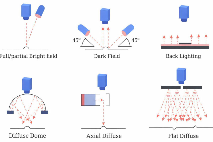
Diffused lighting
Diffused lights reduce harsh reflections and provide uniform illumination. They are essential for:
- Cast surfaces
- Machined but matte finishes
- General surface uniformity checks
Diffusers help suppress unwanted specular highlights, making inspection more stable across parts.
Custom lighting geometry
Standard ring lights are rarely sufficient. Engine inspection often requires:
Bar lights
Placed at controlled angles
Partial ring lights
To avoid glare
Coaxial lighting
For flat reflective faces
Low-angle lighting
For surface defects
The lighting geometry is customized based on surface roughness, material reflectivity, defect orientation, and expected defect size and depth.
Dark-field and low-angle lighting
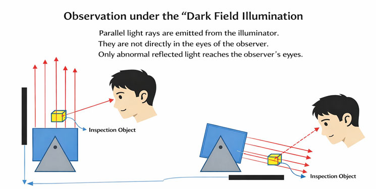
Dark-field illumination is especially powerful for detecting:
- Scratches
- Micro cracks
- Surface pitting
- Burrs and raised edges
Low-angle (grazing) light converts very small height variations into strong optical contrast—making otherwise invisible defects detectable.
Motion systems: enabling complete surface coverage
Linear motion systems
Linear axes are used to:
- Scan long parts such as crankshafts or camshafts
- Move cameras across large surfaces
- Capture consistent images along the length of a part
- Maintain resolution without using ultra-wide optics
Linear motion ensures constant working distance and image scale.
Rotational motion systems
Rotational stages are essential for cylindrical or rotationally symmetric parts:
Shafts, Gears, Sleeves, Valve bodies
As the part rotates:
- The camera captures a continuous or step-wise image sequence
- The full circumference is inspected
- Surface defects are unwrapped digitally for analysis
Rotational motion combined with line-scan or area-scan cameras provides full 360° coverage.
Moving camera, moving light, or moving part?
There is no single correct approach. The choice depends on automation constraints:
Conveyor-based inspection systems for engine components
In high-throughput manufacturing, a conveyor-based inspection system is often required.
When conveyor-based inspection is suitable
- Parts move continuously or index-based on a line
- Inspection must not interrupt takt time
- Vision system must synchronize with existing automation
Design considerations
Controlled inspection zones on the conveyor
Triggering via sensors or encoders
Shielding from ambient lighting
High-speed imaging and processing
Reject or marking mechanisms downstream
Conveyor-based systems must balance speed, precision, and robustness—especially for heavy engine components.
Coordinating vision, motion, and automation
An effective engine inspection system tightly integrates:
Vision algorithms
Lighting control
Motion control
Linear, rotary, or robotic
PLC or robot interfaces
Data logging and traceability systems
The inspection workflow is often:
- Part enters inspection zone
- Motion system positions or rotates the part
- Lighting configuration is applied
- Image(s) are captured
- AI and vision algorithms evaluate defects
- Results are sent to downstream automation
This orchestration is what makes complex inspection repeatable and production-ready.
Designing based on geometry and inspection goals
Every engine component demands a custom inspection strategy based on:
Geometry complexity
Surface type
Defect criticality
Required cycle time
Level of automation
Integration needs
There is no universal template. Successful systems are engineered by:
- Studying the part in detail
- Prototyping imaging and lighting
- Iterating motion paths
- Validating on real production samples
Inspection of engine components using machine vision is inherently complex. It requires:
- Advanced imaging strategies
- Diffused and custom lighting geometries
- Low-angle and dark-field illumination
- Coordinated motion systems (linear, rotational, or combined)
- Conveyor-based or integrated automation when needed
In these systems, cameras, lights, and parts may all move—not as a complication, but as a necessity driven by product geometry and inspection goals.
When designed correctly, such inspection systems deliver consistent defect detection, full surface coverage, and production-ready reliability—turning machine vision into a true quality assurance backbone for engine manufacturing.