Detecting Rubber Flash Defects in Tyre Manufacturing with Visual AI
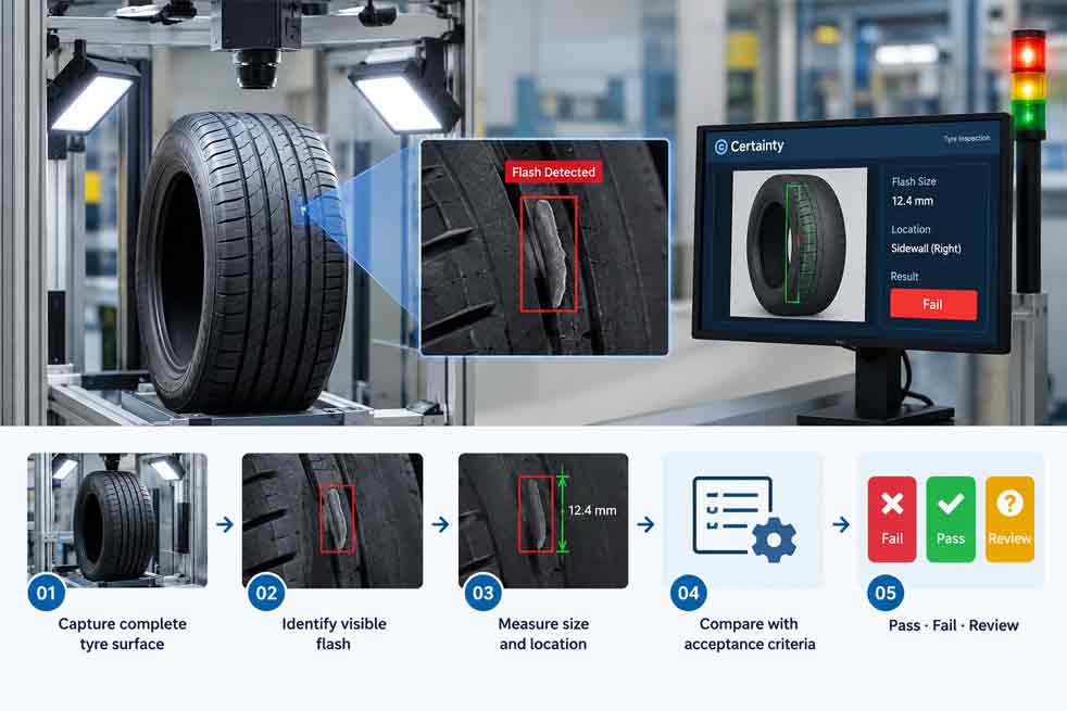
Rubber flash is a common condition in tyre manufacturing. A small amount of flash may be acceptable, but excessive flash can affect the tyre’s appearance, interfere with downstream operations, or indicate a problem with the moulding process.
Intelgic provides an automated solution for detecting and measuring rubber flash using industrial cameras, controlled lighting, state-of-the-art AI, and the Certainty inspection platform.
The system captures images of the complete tyre surface, identifies visible flash, measures its size and location, and compares the result with manufacturer-defined acceptance criteria.
Certainty can then classify the tyre as pass, fail, or review and immediately notify the operator when excessive flash is detected.
What Is Rubber Flash on a Tyre?
Rubber flash is a thin layer, ridge, projection, or excess piece of rubber that extends beyond the intended tyre geometry after moulding and curing.
During tyre curing, the uncured rubber assembly is placed inside a mould. Heat and pressure force the rubber into the mould cavities to form the tread pattern, sidewall markings, shoulders, and other tyre features.
Small amounts of rubber can be forced into gaps where mould sections meet or through openings used to release trapped air. Once cured, this rubber remains attached to the tyre as flash.
Depending on its location and shape, flash may appear as:
Flash should be distinguished from tyre features that are intentionally created by the mould and are acceptable within the manufacturer’s specification.
How Tyre Flash Is Created
Rubber flash can be influenced by several moulding and process conditions.
Tyre moulds contain sections that open and close around the tyre. Small gaps can exist where these sections meet. During curing, pressurised rubber may enter these gaps and form a thin ridge along the parting line.
Segmented tread moulds contain multiple sections. Rubber may enter the joint between adjacent segments and create flash across or between tread features.
Mould vents allow trapped air and gases to escape during curing. Rubber can enter these small openings and create narrow projections commonly referred to as vent spews or vent hairs.
Worn, damaged, contaminated, or incorrectly fitted mould components may create larger gaps that allow excessive rubber to escape.
If the mould does not close or align correctly, excessive material may form at the joint.
Rubber volume, temperature, pressure, curing conditions, compound behaviour, and material placement can influence flash formation.
Rubber residue or foreign material between mould surfaces may prevent proper closure and create a local flash condition.
Some vent projections are expected and acceptable. The inspection system must distinguish normal vent features from excessive, damaged, or otherwise unacceptable rubber projections according to the tyre manufacturer’s criteria.
Where Flash Appears on a Tyre
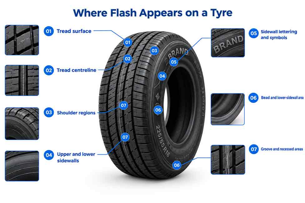
Flash can appear on several tyre regions.
Flash may form between mould segments, across tread blocks, inside grooves, around sipes, or near vent locations.
Some mould configurations create a visible parting line or flash around the centre of the tread.
The transition between the tread and sidewall can contain mould joints and complex geometry where excess rubber may appear.
Flash can develop along sidewall mould joints, around decorative features, near lettering, and around raised markings.
Excess rubber may appear around:
Flash may appear close to the bead, bead toe, bead heel, rim-contact region, or lower-sidewall mould joint.
Thin excess material may form inside deep grooves, around small cavities, or between fine moulded features.
Because these areas have different shapes and viewing angles, one camera may not provide complete inspection coverage.
Acceptable and Unacceptable Flash
The presence of flash does not automatically mean that a tyre is defective.
Tyre manufacturers normally define acceptance tolerances based on factors such as:
A small amount of flash may be acceptable in one region but unacceptable in another. For example, a defined projection at a vent location may be allowed, while excess rubber interfering with a groove or bead surface may not be acceptable.
Within Intelgic’s Certainty platform, users can define the acceptance criteria for each tyre model and inspection region. The AI detects visible flash, while the configured rules determine whether its measured size and location are acceptable.
Challenges in Inspecting Tyre Flash
Tyres are difficult to inspect because they are dark, curved, textured, and covered with intentional moulded features.
Important challenges include:
Intelgic addresses these challenges using multiple cameras, controlled camera geometry, specialized lighting, complete circumferential imaging, AI-based defect detection, and configurable acceptance criteria.
Intelgic’s Visual AI Solution for Tyre-Flash Detection
Intelgic’s solution captures images of the complete tyre surface and analyzes them using state-of-the-art AI trained on representative tyre-production data.
The inspection system can:
The final inspection capability depends on the minimum flash size, tyre geometry, camera resolution, lighting, surface condition, production speed, and validated acceptance criteria.
Solution 1: Stationary Tyre-Inspection System
In a stationary inspection system, the tyre is mounted on a rotating fixture. The fixture rotates the tyre while multiple cameras capture images from strategically selected positions.
This configuration provides controlled movement and repeatable imaging of the complete tyre circumference.
Rotating tyre fixture
The fixture holds and rotates the tyre at a controlled speed. An encoder can synchronize tyre rotation with image capture, allowing every image to be linked to an angular position.
The fixture design depends on:
Tyres may be loaded manually, by a robot, or through an automated material-handling system.
Multiple-camera coverage
Several cameras are positioned around the tyre to inspect different surfaces. A typical configuration may include cameras for:
Camera quantity and position are selected according to the tyre geometry, required resolution, and minimum detectable flash size.
Image acquisition during rotation
As the tyre rotates, the cameras capture overlapping images or continuous line-scan data. Certainty synchronizes:
The captured images provide complete circumferential coverage of the defined inspection regions.
Detailed inspection report
After image analysis, Certainty can generate a report containing:
The report can map each detected flash condition to its angular and regional position on the tyre.
Solution 2: Conveyor-Based Tyre Inspection
In a conveyor-based manufacturing line, tyres move through the inspection station without being manually mounted on a dedicated rotating fixture.
Industrial cameras are installed at strategic positions around the conveyor. Sensors detect an approaching tyre and trigger the cameras when it enters the correct field of view.
Camera placement around the conveyor
Multiple cameras may be installed to inspect:
Mirrors, additional camera stations, tyre-turning mechanisms, or controlled tyre rotation may be used when direct camera access is limited.
Triggered image capture
A photoelectric sensor, encoder, PLC signal, barcode reader, or tracking system identifies the tyre’s position.
Multiple images are captured as the tyre moves through the field of view. The system associates the images with the correct tyre identity and production record.
Complete surface coverage
A conveyor inspection system must be designed around how the tyre is presented. If the tyre moves without rotating, the visible areas may be inspected using cameras located around the conveyor. When the complete circumference must be examined at high resolution, the line may include:
The imaging architecture is selected according to the production layout, cycle time, available space, and required surface coverage.
Area-Scan and Line-Scan Imaging
Area-scan cameras capture a complete two-dimensional image at each trigger. They are suitable when:
A line-scan camera captures one narrow line of pixels at a time. Controlled tyre movement or rotation builds a continuous, unwrapped image of the tread or sidewall circumference. This makes it easier to:
The correct camera type depends on the tyre geometry, required resolution, defect size, and production speed.
State-of-the-Art AI for Flash Detection
Traditional image-processing algorithms can struggle to separate flash from normal tread texture, lettering, vent features, and moulded edges.
Intelgic’s AI learns these visual differences using representative images of acceptable and unacceptable tyres. Depending on the application, the AI may perform:
Determines whether an image region contains flash or an acceptable tyre feature.
Locates individual flash conditions within the image.
Identifies the pixels associated with the flash so that its visible dimensions and area can be measured.
Flags regions that differ from validated examples of acceptable tyre surfaces, including unexpected excess-rubber conditions.
Compares images captured under different lighting directions to separate real flash from shadows and normal moulded features.
Applies different inspection rules depending on whether the flash appears on the tread, shoulder, sidewall, bead, lettering, or another defined region.
Defining Flash Acceptance Criteria in Certainty
Certainty allows users to configure acceptance rules for each tyre model and inspection area. Criteria may include:
Acceptance rules can be different for each tyre size, pattern, mould, customer, or product grade.
The AI detects and measures the visible condition. Certainty applies the active rules and determines whether the tyre should pass, fail, or be reviewed.
Recipe Management for Different Tyre Models
Tyres differ in:
Certainty can maintain a separate inspection recipe for each tyre variant.
What a recipe may control
The correct recipe can be loaded automatically using a barcode, RFID tag, PLC signal, MES work order, tyre marking, or verified operator selection.
How the Inspection Process Works
Operator Alerts and Defect Visualization
When the AI detects flash outside the permitted tolerance, Certainty can display:
This helps the operator locate the defect quickly instead of manually searching the complete tyre surface.
Digital Tyre Inspection Records
Certainty can create a digital record for every inspected tyre. The record may include:
These records support traceability, production analysis, quality audits, and mould-maintenance decisions.
Integration with Existing Manufacturing Systems
Certainty can be integrated with existing factory automation and production software.
PLC integration
The platform can exchange:
MES integration
MES connectivity can support:
ERP and quality-system integration
Certainty can also connect with:
Cloud-Based Tyre Quality Analytics
Inspection results can be transferred to a secure cloud analytics environment, subject to the manufacturer’s cybersecurity and data-governance policies.
- ✓Tyres inspected
- ✓Pass and fail rates
- ✓Flash defects by category
- ✓Flash dimensions
- ✓Defects by tyre model
- ✓Defects by tyre region
- ✓Defects by mould
- ✓Defects by curing press
- ✓Defects by production line
- ✓Defects by shift
- ✓Rework frequency
- ✓Quality trends over time
- ✓Flash defect heat maps
- ✕Mould-segment joints
- ✕Parting surfaces
- ✕Vent conditions
- ✕Mould wear
- ✕Mould alignment
- ✕Closure problems
- ✕Contamination
- ✕Process parameters
Aggregated defect locations can reveal where excess rubber repeatedly appears.
These insights can help maintenance and quality teams investigate the process before the condition becomes more severe.
Benefits of Automated Tyre-Flash Inspection
The system evaluates every tyre using the same imaging method and acceptance criteria.
Multiple cameras and controlled tyre movement allow the tread, sidewalls, shoulders, and bead regions to be inspected.
Manufacturers can define different flash limits for each tyre model and surface region.
Annotated images and tyre maps show operators where unacceptable flash was detected.
Inspection images, measurements, recipes, and results can be associated with each tyre.
Analytics can identify recurring flash locations and possible mould or curing-process problems.
Automation performs repetitive surface inspection while quality personnel focus on uncertain results and final disposition.
Important Measurement Considerations
A standard 2D camera measures visible image dimensions. Accurate physical measurement requires:
Because tyres are curved, a two-dimensional image may not reliably measure flash height extending away from the surface in every orientation.
When 3D height or volume matters
When actual three-dimensional height or volume is part of the acceptance criterion, the system may require:
Intelgic can integrate these sensors with Certainty when both visual detection and dimensional measurement are required.
Important Inspection Limitations
Visual AI detects flash that is visible to the selected cameras and lighting system. Detection can be affected by:
The inspection architecture and AI model must be validated using representative tyre sizes, tread patterns, compounds, mould features, acceptable flash, and rejectable flash.
The tyre manufacturer remains responsible for defining acceptance limits and final product disposition.
Validating a Tyre-Flash Inspection System
Validation should include:
The system should generate a review-required result when the available image does not provide sufficient evidence for a reliable decision.
Tyre-Flash Detection from Intelgic
Intelgic combines industrial cameras, rotating fixtures or conveyor-based imaging, specialized lighting, state-of-the-art AI, and the Certainty inspection platform to detect rubber flash defects in tyre manufacturing.
For stationary inspection, a tyre is mounted on a fixture and rotated while multiple strategically positioned cameras capture the tread, shoulders, sidewalls, bead regions, and other required surfaces.
For conveyor-based inspection, cameras are positioned around the production line and triggered as each tyre enters the defined field of view. Multiple images provide the coverage required for flash detection.
Certainty identifies each flash condition, applies user-defined acceptance tolerances, alerts the operator when excessive flash is detected, and generates a detailed digital inspection report.
Looking to automate tyre-flash inspection? Contact Intelgic to discuss a stationary or conveyor-based Visual AI inspection system powered by the Certainty platform.
Frequently Asked Questions
What is a rubber flash on a tyre? +
Rubber flash is excess cured rubber that extends beyond the tyre’s intended geometry. It may appear as a thin ridge, fin, projection, or sheet near mould joints, vents, tread features, sidewalls, shoulders, or bead areas.
Why does flash form during tyre manufacturing? +
Flash forms when uncured rubber enters small gaps between mould sections or vent openings during curing. Mould wear, misalignment, contamination, material volume, pressure, and other process conditions can influence its formation.
Is all tyre flash considered defective? +
No. Manufacturers normally allow a defined amount of flash in specified areas. Certainty compares the detected flash with the configured tolerance for the tyre model and surface region.
How does the stationary inspection system work? +
The tyre is mounted on a rotating fixture. Multiple cameras capture images of the tread, shoulders, both sidewalls, bead regions, and other required surfaces while the tyre rotates.
Can tyres be inspected while moving on a conveyor? +
Yes. Cameras can be installed at strategic locations and triggered as tyres enter their fields of view. Multiple cameras and images are used to cover the required tyre surfaces.
Can the system inspect the complete tyre circumference? +
Yes. A rotating fixture, controlled rotation on the conveyor, line-scan imaging, or multiple imaging positions can be used to capture the complete circumference.
Can AI distinguish flash from normal vent spews? +
Yes, when the system is trained and validated using representative examples. Certainty can apply separate acceptance rules for normal vent features and excessive rubber projections.
Can Certainty measure the size of the flash? +
Yes. A calibrated imaging system can measure visible length, width, and area. A 3D sensor may be required when actual height or volume must be measured on a curved surface.
Can different flash tolerances be applied to different tyre regions? +
Yes. Certainty can apply different criteria to the tread, shoulder, sidewall, lettering, bead, vent locations, and other defined inspection regions.
Can Certainty integrate with existing PLC and MES systems? +
Yes. Certainty can exchange tyre identity, recipes, machine status, inspection results, alarms, reject commands, and traceability information with existing manufacturing systems.