Robotic Inspection of Engine-Block Cylinder Bores for Scratches, Scoring and Surface Defects
Intelgic automates engine-block cylinder-bore inspection by combining robots or collaborative robots, specialized bore-imaging devices, industrial machine-vision cameras, controlled lighting, state-of-the-art AI, and the Certainty inspection platform.
The robot moves the imaging device to each cylinder and aligns it with the bore. Depending on the bore diameter, depth, surface finish, and required defect resolution, the system can use a borescope-style camera, an area-scan camera with specialized optics, or a line-scan imaging arrangement.
Certainty loads the correct inspection recipe for the engine-block variant, controls the robot and imaging sequence, and sends the captured images to Intelgic's AI. The AI analyzes the internal surface for scratches, scoring, cracks, pitting, honing irregularities, contamination, and other defined defects.
Each detected condition is mapped to its position inside the bore and stored with the engine block's inspection record.
Challenges
Cylinder bores are among the most difficult machined surfaces to inspect automatically. Their internal geometry restricts camera access, while the metallic finish produces reflections that can hide defects or make normal machining patterns appear defective.
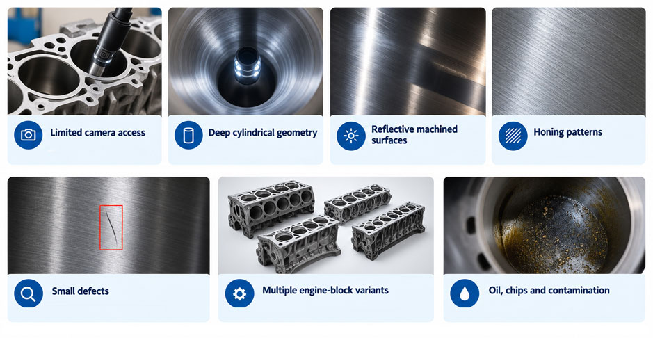
Limited camera access
The inspection device must enter or view through the cylinder opening while maintaining sufficient clearance from the bore wall. Camera, lens, lighting, cables, and protective housing must fit within the available diameter.
Deep cylindrical geometry
A single image cannot normally capture the complete circumference and depth of a cylinder bore at the resolution needed for small surface defects. The imaging device must scan through the bore, rotate around its axis, use panoramic optics, or capture multiple overlapping views.
Reflective machined surfaces
Finished cylinder walls reflect light differently as the camera moves. Bright glare can hide scratches, while dark reflections can resemble scoring or cracks.
Honing patterns
Cylinder bores commonly contain intentional crosshatch or plateau-honing patterns. These regular machining marks must be distinguished from abnormal scratches, scoring, chatter, and tool damage.
Small defects
Fine scratches, pores, pits, tears, and cracks may occupy only a small number of pixels. The camera resolution, lens, working distance, lighting, and motion stability must all support the required defect size.
Multiple engine-block variants
Cylinder count, bore diameter, bore depth, spacing, deck geometry, liner material, and surface finish can vary between engine models. The system must load the correct robot positions, imaging parameters, and inspection criteria for every variant.
Oil, chips and contamination
Residual coolant, honing oil, metal chips, lint, dust, and cleaning marks can hide genuine defects or create false indications. The component must be presented in a surface condition consistent with the validated inspection process.
How Intelgic Addresses the Challenges
Intelgic develops the inspection architecture around the engine block, bore geometry, manufacturing process, required defect size, and production cycle.
The system uses robotic positioning to align the imaging device with each bore. Controlled illumination is directed onto the internal wall, and multiple images or continuous scan data are captured across the full required surface.
Specialized bore-imaging device
The imaging head may include:
The correct configuration depends on whether the inspection requires a rapid general view or detailed imaging of the complete internal surface.
Controlled lighting
Lighting must reveal abnormal defects without causing excessive glare from the machined metal. Intelgic may use:
Different lighting conditions reveal different surface characteristics. A fine scratch may become visible under directional illumination, while a pit or pore may appear more clearly under diffuse lighting.
Multiple images under different lighting conditions
The system can capture several images of the same bore region while activating different lights. Intelgic's AI compares the complementary images to distinguish physical defects from reflections and normal surface texture.
Full internal-surface coverage
The bore is divided into inspection zones based on depth and circumference. The imaging sequence may use:
Certainty associates every image with its location inside the cylinder.
Area-Scan Bore Inspection
An area-scan camera captures a complete rectangular image at each inspection position.
The robot or precision motion system moves the camera through the bore and captures multiple overlapping views. The camera may use side-view optics to image sections of the internal wall.
Area-scan imaging is suitable when:
The system can capture a general image first and then acquire higher-resolution images of selected areas.
How the Robotic Inspection Process Works
Robot and Cobot Inspection Configurations
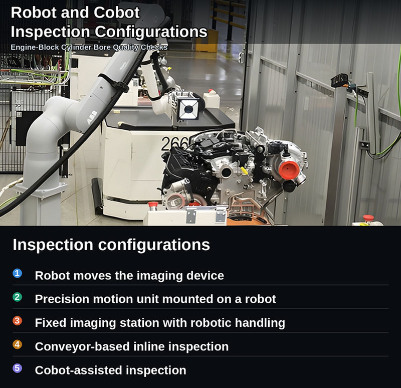
Robot moves the imaging device
A robot positions the camera or probe at each cylinder and performs the required scan. This arrangement is suitable for engine blocks containing several bores or variants with different cylinder positions.
Precision motion unit mounted on a robot
The robot provides bore-to-bore positioning, while a dedicated linear or rotary mechanism performs the controlled internal scan. This separates general robotic movement from the precise motion required for image reconstruction.
Fixed imaging station with robotic handling
A robot picks the engine block and presents each bore to a fixed inspection device. This may be suitable for smaller blocks that can be handled safely within the robot's payload and inertia limits.
Conveyor-based inline inspection
The engine block arrives on a conveyor, pallet, or transfer system. A lift-and-locate station positions it accurately before the robotic scan begins. After inspection, the system returns the part to the line or routes it for rework.
Cobot-assisted inspection
A cobot can be used for lower-speed, flexible, or offline inspection where operators load engine blocks or where the system must accommodate frequent product changes. The complete application still requires an appropriate safety assessment.
Certainty Inspection Platform
Certainty manages the complete robotic bore-inspection workflow. It coordinates:
Recipe Management for Engine-Block Variants
A manufacturing line may produce engine blocks with different cylinder counts, bore sizes, materials, and surface finishes. Certainty can maintain a separate recipe for each variant.
The correct recipe can be loaded automatically using the part identity or manufacturing order. This allows the system to change:
Automatic recipe loading reduces manual setup and helps prevent inspection using the wrong configuration.
Integration with Existing Systems
Certainty can be integrated with existing factory automation and manufacturing software.
PLC integration
The platform can exchange:
MES integration
MES connectivity can support:
Additional connectivity
Certainty can also connect with:
Cloud-Based Quality Inspection Analytics
Inspection results can be transferred to a secure cloud analytics environment, subject to the manufacturer's cybersecurity and data-governance requirements.
Quality dashboards
Dashboards may display:
Bore defect heat maps
Aggregated defect locations can reveal whether scratches, scoring, chatter, or surface irregularities repeatedly occur at the same depth or angular position. These patterns may indicate problems involving:
Image-level traceability
Authorized users can review original images, annotated defects, measurements, AI confidence, bore location, inspection recipe, and production history.
Digital Inspection Records
For each engine block, Certainty can record:
State-of-the-Art AI for Bore Defect Detection
Cylinder walls contain complex machining patterns that can be difficult to evaluate with fixed image-processing thresholds.
Intelgic's AI learns the difference between acceptable surface texture and defined defects using representative production images. Depending on the application, the AI may perform:
Defect classification
Determines whether an inspection region contains scoring, a scratch, crack, pit, pore, chatter, contamination, or another trained defect.
Object detection
Locates the defect within the captured image.
Segmentation
Identifies the pixels associated with the defect, allowing the visible length, width, and area to be calculated.
Anomaly detection
Flags regions that differ from validated examples of acceptable honed surfaces, including unexpected conditions not assigned to a predefined class.
Texture analysis
Evaluates the consistency of the machining or honing pattern and identifies unusual interruptions or local changes.
Multi-image analysis
Compares images captured under different lighting conditions to separate physical defects from glare and normal reflectivity.
AI provides results according to the validated inspection method and configured quality criteria. It does not independently define whether a bore is acceptable.
Defects That Can Be Detected
An automated optical system can be configured to detect visible defects and surface conditions. Actual performance depends on camera resolution, lighting, bore geometry, cleanliness, defect size, and validated acceptance criteria.
Scratches
Scratches may be produced during machining, washing, handling, gauging, assembly, or transport. The system can record their visible:
Scoring
Scoring generally appears as pronounced linear damage running along the cylinder wall. The AI can distinguish defined scoring patterns from the normal crosshatch finish when trained and validated with representative examples.
Cracks
Some open surface cracks can be detected using high-resolution imaging and directional lighting. Very fine, closed, subsurface, or contamination-filled cracks may require another suitable and approved inspection method.
Pits and porosity
The system can identify visible cavities, pores, blowholes, and localized material loss on the bore surface.
Honing defects
Possible conditions include:
Optical inspection can identify appearance anomalies, while the measurement of parameters such as surface roughness may require dedicated metrology equipment.
Chatter marks
Periodic or repeating surface patterns may indicate vibration during boring or honing. Defect analytics can help correlate recurring chatter with a particular machine, tool, spindle, or production period.
Burrs and edge damage
The bore entrance, chamfer, ports, and liner edges can be checked for burrs, chips, nicks, and material deformation.
Corrosion and discoloration
Visible oxidation, staining, corrosion products, and abnormal color changes can be classified when they differ reliably from acceptable material variation.
Contamination and foreign material
The system may detect:
Liner-related surface conditions
Where cylinder liners are used, the inspection can check for visible:
Intelgic already applies specialized cameras, robotic motion, controlled lighting, and AI software to automate the inspection of bores and internal metal surfaces. Its bore-inspection approach is customized according to bore size, surface condition, defect type, and production requirements. Looking to automate engine-block cylinder-bore inspection? Contact Intelgic to discuss a robotic machine-vision and AI inspection system powered by the Certainty platform.
Frequently Asked Questions
How does Intelgic inspect the complete cylinder-bore surface? +
The imaging device moves through the bore while capturing multiple area-scan images or continuous line-scan data. Rotary, axial, panoramic, or helical scanning can provide the required circumferential and depth coverage.
Can AI distinguish scoring from normal honing marks? +
Yes, when the system is trained and validated using representative images of acceptable honing patterns and actual scoring defects.
Can the system inspect different engine-block models? +
Yes. Certainty stores variant-specific recipes containing bore positions, dimensions, robot paths, camera settings, lighting sequences, AI models, and inspection criteria.
Can a robot inspect multiple cylinders automatically? +
Yes. The robot moves the imaging device from one cylinder to the next and performs the required scan according to the loaded recipe.
Can machine vision measure bore diameter and roundness? +
Not with ordinary 2D surface imaging alone. Suitable dimensional sensors, air gauges, or metrology systems can be integrated when these measurements are required.
Can the system identify the depth and angular position of a defect? +
Yes. When imaging is synchronized with the linear and rotary motion, Certainty can map the defect to a cylinder number, bore depth, and circumferential position.
Can Certainty integrate with an existing PLC and MES? +
Yes. Certainty can exchange part identity, recipe, machine status, inspection results, alarms, traceability data, and rework information with existing systems.
Are inspection results available through cloud dashboards? +
Yes. Subject to the manufacturer's data policies, dashboards can display defect trends, bore heat maps, images, pass/fail rates, inspection cycle time, and production-quality metrics.