Robotic Inspection of Bolted Joints in Large Automotive and Aircraft Parts
Intelgic automates the inspection of bolted joints on large automotive and aircraft components by combining industrial robots or collaborative robots, high-resolution machine-vision cameras, specialized lighting, 3D sensors, state-of-the-art AI, and the Certainty inspection platform.
Large components are divided into multiple inspection regions. A robot moves the camera and lighting assembly to every location where a bolt, nut, washer, locking feature, or related assembly detail must be inspected. Certainty loads the correct recipe for the part variant, controls the imaging sequence, and sends the captured images to Intelgic's AI for defect detection.
The system can inspect bolted joints for presence, position, visible damage, incorrect components, improper seating, gaps, missing locking features, and other defined assembly conditions. Every result is mapped to its physical location and stored for traceability and quality analytics.
Challenges
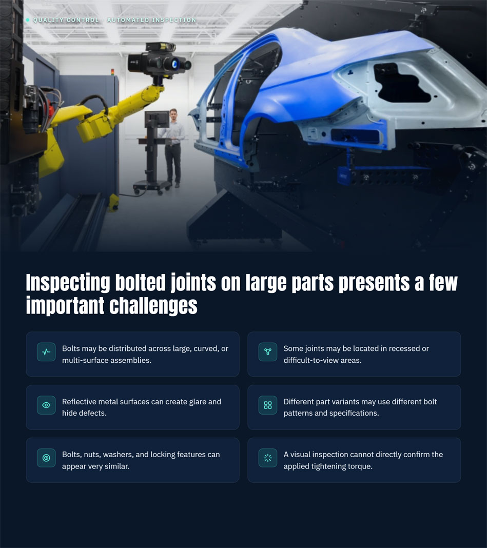
Inspecting bolted joints on large parts presents a few important challenges:
How Intelgic Addresses These Challenges
Intelgic divides the component into defined inspection regions and creates a robotic imaging path for each region.
The robot positions the camera at the correct distance and angle for each bolted joint. Controlled lighting improves the visibility of the bolt head, nut, washer, surrounding surface, and any torque or locking marks.
For reflective or complex joints, Intelgic's Certainty AI platform can capture multiple images using different lighting conditions. Intelgic's AI then analyzes the images to distinguish actual assembly defects from glare, shadows, surface texture, and acceptable variation.
Different inspection recipes can be created for every automotive or aircraft component variant. The correct recipe can be loaded automatically using the part identity or production order.
Robotic Inspection of Large Parts
Large components cannot normally be inspected with one fixed camera while maintaining sufficient resolution across every bolted joint. Examples include:
A robot or cobot allows the camera to move between joints located on different surfaces and at different orientations.
Component divided into inspection regions
The part is divided into smaller regions based on:
Each region can have its own camera position, exposure, focus, lighting sequence, AI model, and acceptance criteria.
Robot mounted on a linear track
When the component is longer than the robot's working envelope, the robot can be installed on a linear track. Certainty coordinates the robot and track positions so the imaging device can cover the complete component.
Multiple-robot inspection
Two or more robots may be used when:
Robot moves the component
For parts within the robot's payload and inertia limits, the robot can hold the component and present its bolted joints to stationary cameras and lights.
Hybrid inspection system
Fixed cameras can inspect easily accessible joint groups, while a robot-mounted camera examines recessed, angled, or critical locations.
Multiple images under different lighting conditions
Certainty can activate several lights sequentially while the robot remains at the same inspection position. For example, it may capture:
Intelgic's AI analyzes the combined image set to distinguish physical defects from reflections.
How the Robotic Inspection Process Works
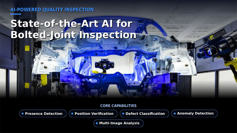
State-of-the-Art AI for Bolted-Joint Inspection
Traditional machine vision works well when a feature can be inspected using fixed rules for position, diameter, color, or shape. Bolted assemblies are more complex because joint appearance can vary with surface finish, bolt orientation, coatings, reflections, torque marks, sealants, and acceptable manufacturing variation.
Intelgic's AI learns these visual patterns using representative images of acceptable and defective assemblies. Depending on the application, the AI may perform:
Presence detection
Confirms the presence of the required:
Position verification
Compares the joint's actual location and orientation with the nominal assembly position.
Defect classification
Identifies trained conditions such as a damaged bolt head, missing washer, incorrect locking feature, or abnormal seating.
Anomaly detection
Flags a joint that differs from validated examples of acceptable assemblies, including unusual conditions not included in a predefined defect category.
Multi-image analysis
Compares images taken under different lighting or viewing conditions to reduce false detections caused by reflections.
Machine vision cannot directly measure torque or preload. It can inspect visible seating, gaps, thread projection, torque marks, and locking features — not the applied tightening force.
Intelgic's Certainty AI Inspection Platform's Capability
Certainty manages the complete bolted-joint inspection workflow. It coordinates:
Integration with Existing Systems
Certainty can be integrated with existing factory automation and manufacturing software.
PLC integration
The platform can exchange:
MES integration
MES connectivity can support:
Additional connectivity
Certainty can also connect with ERP systems, SCADA, quality-management platforms, factory databases, data historians, cloud systems, and customer-specific applications.
Cloud-Based Quality Inspection Analytics
Inspection data can be transferred to a secure cloud analytics environment, subject to the manufacturer's cybersecurity and data-governance policies. Dashboards may display:
Image-level traceability
Authorized users can review the original image, annotated defect, measurement result, AI confidence, inspection recipe, and production history for any joint.
The inspection architecture is customized around the component size, shape, joint locations, production cycle, minimum defect size, and existing manufacturing systems. Looking to automate bolted-joint inspection on large automotive or aerospace components? Contact Intelgic to discuss a robotic machine-vision and AI inspection system powered by the Certainty platform.
Frequently Asked Questions
Can AI detect missing bolts, nuts, and washers? +
Yes. Certainty compares every expected joint location with the captured images and identifies missing or visibly incorrect components.
Can machine vision determine whether a bolt is tight? +
No. Machine vision cannot directly measure torque or preload. It can inspect visible seating, gaps, thread projection, torque marks, and locking features.
Can Certainty combine torque-tool and camera data? +
Yes. Fastening-controller data can be associated with the visual inspection result to create a more complete joint record.
Can the system inspect very large components? +
Yes. Large components can be inspected using long-reach robots, robots on linear tracks, multiple robots, or hybrid fixed-camera and robotic systems.
Can one cell inspect different component variants? +
Yes. Certainty can store separate bolt maps, robot paths, camera settings, lighting sequences, AI models, and inspection criteria for each variant.
Can the system inspect recessed bolts? +
Yes, when the camera, optics, lighting, and robot can access the location. Some deeply recessed or obstructed joints may require compact or angled imaging equipment.
Can defects be displayed on a component map? +
Yes. Certainty can link every bolted-joint result to its location on a digital representation of the component.
Can Certainty integrate with an existing PLC and MES? +
Yes. Certainty can exchange component identity, recipes, machine status, inspection results, alarms, traceability, and rework information with existing systems.
Are results available through cloud dashboards? +
Yes. Subject to the manufacturer's data policies, dashboards can display joint defects, heat maps, images, pass/fail rates, rework data, and production-quality trends.