Robotic Inspection of Aircraft Windows for Cracks, Scratches and Delamination
Intelgic automates aircraft-window inspection by combining industrial robots or collaborative robots, high-resolution machine-vision cameras, specialized lighting, state-of-the-art AI, and the Certainty inspection platform.
Cracks, scratches, crazing, coating damage, edge defects, and visible delamination may appear differently depending on the camera angle and direction of illumination. Some defects are visible only when light passes through the window, while others become clearer under low-angle or dark-field lighting.
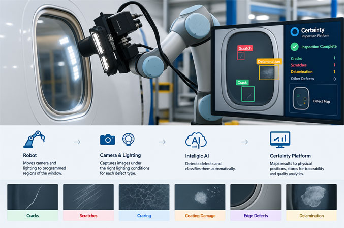
The robot moves the camera and lighting system to programmed regions of the window. Certainty automatically controls the imaging recipe for each location, captures images under the required lighting conditions, and sends them to Intelgic's AI for defect detection. Results are mapped to their physical positions and stored for traceability and quality analytics.
Challenges
Aircraft windows can be manufactured from acrylic, polycarbonate, glass, interlayer materials, coatings, and other approved transparent materials. The FAA notes that aircraft windows and windshields require specialized engineering because transparent materials do not behave in the same way as conventional metallic structures. See FAA AC 25.775-1.
Several optical and production factors make inspection difficult.
Transparent surfaces
The camera may capture features on the front surface, inside the material, on an interlayer, or on the rear surface simultaneously. The inspection system must determine which features are relevant.
Reflections and glare
Lights, cameras, operators, machinery, and surrounding structures can appear as reflections in the window. These reflections may hide defects or resemble cracks and scratches.
Curved geometry
Curved windows change the reflection angle, focus, magnification, and optical path across the surface. A lighting arrangement that works at the center may not work near an edge.
Multilayer construction
A laminated window may contain several transparent plies, coatings, heating elements, interlayers, films, and edge seals. Delamination can develop at different depths and may have a different appearance depending on its location.
Small defects
Fine scratches, cracks, crazing, chips, bubbles, and coating imperfections may be difficult to distinguish from dust, fibers, water spots, or normal material texture.
Multiple window variants
Passenger windows, cockpit windows, door windows, observation windows, and other transparent components can have different shapes, dimensions, materials, curvatures, and acceptance limits.
How Intelgic Addresses the Challenges
Intelgic uses specialized lighting with a controlled environment and robotics to traverse the camera through the surface and detect defects from different angles.
Controlled inspection environment
Aircraft-window inspection should be conducted in an optically controlled environment. Uncontrolled factory lighting can introduce changing reflections, shadows, and background objects.
A dark or enclosed inspection cell allows the system to control the light that reaches the camera. Benefits include:
Dividing the window into inspection regions
A high-resolution image of an entire window may not provide enough pixels across the smallest required defect. The window is therefore divided into multiple inspection regions based on:
Adjacent images can overlap to ensure that no part of the required surface falls between inspection regions.
How the Robotic Inspection Process Works
Robot or Cobot Inspection Configurations
Camera moves around a stationary window
A robot carries the camera and lighting assembly around a window held in a fixture. This is useful for large, curved, or complex windows requiring many viewing angles.
Robot moves the window
For smaller windows, the robot may hold the component and present it to stationary cameras and lights. This arrangement can provide highly repeatable imaging positions and keep the camera equipment fixed.
Dual-robot inspection
One robot can hold or position the window while another carries the imaging system. This provides flexibility for complex geometry but requires careful synchronization and calibration.
Robot on a linear axis
For large windows or multiple components, a robot can be mounted on a track to extend its inspection coverage.
Fixed-camera and robotic hybrid system
Fixed cameras can perform rapid general inspection, while a robot-mounted camera captures detailed images of critical regions or suspected defects.
State-of-the-Art AI for Defect Detection
Traditional vision algorithms work well for predictable features that can be measured using fixed thresholds.
Aircraft-window defects are often irregular and may appear differently across materials, curvatures, and lighting conditions. AI can learn these complex visual patterns from representative inspection images.
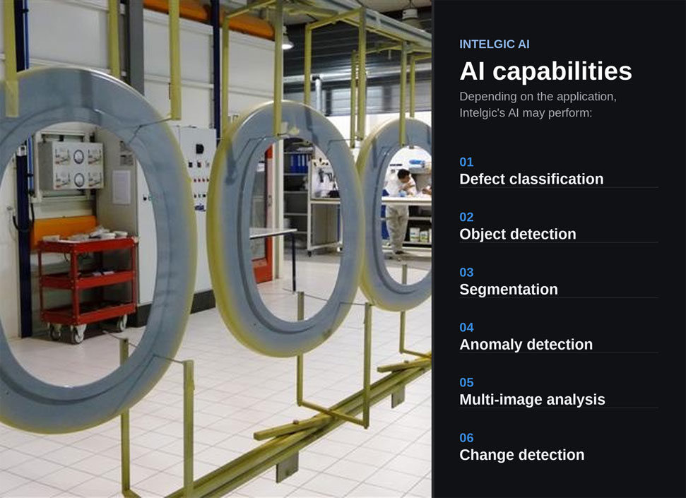
Depending on the application, Intelgic's AI may perform:
Defect classification
Determines whether a region contains a scratch, crack, crazing, delamination indicator, chip, bubble, coating defect, or other trained condition.
Object detection
Locates defects within an image and places a boundary around the affected area.
Segmentation
Identifies the individual pixels associated with a defect, allowing its visible area and dimensions to be calculated.
Anomaly detection
Flags regions that differ from validated examples of acceptable windows, including unexpected conditions not represented by a predefined defect class.
Multi-image analysis
Compares images captured using different lighting arrangements to separate real defects from reflections.
Change detection
When approved baseline images are available, the software can compare inspections over time and identify visible changes.
AI does not independently determine airworthiness. It produces results according to the validated inspection method, configured acceptance criteria, and applicable quality process.
Certainty Inspection Platform
Certainty acts as the central coordination and data-management platform for the automated inspection cell. It manages:
Recipe Management for Different Window Variants
Aircraft-window size, shape, material, curvature, coating, and defect requirements can vary between models. Certainty can maintain an individual recipe for each window variant. A recipe may control:
The correct recipe can be loaded automatically using the part identity or manufacturing order.
Integration with Existing Systems
Certainty can be integrated with existing factory automation and manufacturing software.
PLC integration
The platform can exchange:
MES integration
MES connectivity can support:
Additional connectivity
Certainty can also connect with:
Cloud-Based Quality Inspection Analytics
Inspection results can be transferred to a secure cloud analytics environment, subject to the manufacturer's cybersecurity and data-governance policies.
Quality dashboards
Dashboards may display:
Image-level traceability
Authorized users can review original images, annotated defect images, measurement results, lighting conditions, AI confidence, and inspection history.
Multi-site quality monitoring
Cloud analytics can provide authorized teams with consolidated quality information across production lines, suppliers, and manufacturing locations.
Where cloud storage is restricted, an on-premises or hybrid architecture can retain sensitive images locally while sharing approved statistics.
Digital Inspection Records
For each window, Certainty can record:
Visual Detection of Delamination: Important Limitations
Optical inspection is effective when delamination creates a visible change such as haze, separation, bubbles, interference patterns, discoloration, or edge lifting.
However, machine vision cannot guarantee the detection of every internal separation. Some delamination may produce little or no visible surface indication.
Additional methods may be required depending on the window construction and approved inspection procedure, potentially including:
The aircraft or component manufacturer's maintenance instructions define acceptable limits and required actions. FAA guidance likewise directs users to the relevant manufacturer's manuals for delamination and scratch limits.
Defects That Can Be Detected
An automated optical system can be configured to detect visible defects and surface conditions. Actual capability depends on image resolution, lighting, window material, curvature, cleanliness, defect depth, and validated inspection criteria.
Cracks
Cracks can appear as sharp lines that alter transmitted or reflected light. They may begin at an edge, fastener location, machined feature, or damaged surface. The system may evaluate:
Cracks that are closed, extremely fine, hidden by a coating, or located at an unfavorable depth may require a specialized or approved inspection method.
FAA maintenance guidance distinguishes cracks from surface crazing and recommends consulting the relevant manufacturer's maintenance manual for window inspection limits. FAA AC 20-76 also defines delamination as separation between adjacent laminate layers.
Scratches
Scratches are surface defects that may be caused by manufacturing, handling, cleaning, installation, tools, or foreign particles. Machine vision can detect and measure visible characteristics such as:
A conventional 2D image cannot reliably determine scratch depth. If depth is part of the acceptance criterion, a calibrated 3D, confocal, interferometric, or other suitable measurement method may be required.
Crazing
Crazing consists of networks of very fine surface or near-surface fissures. It may be associated with stress, chemical exposure, ultraviolet degradation, or improper handling. AI can be trained to distinguish crazing patterns from individual scratches, fibers, and background texture when the imaging system provides sufficient contrast.
Visible delamination
Delamination is the separation of adjacent layers within a laminated transparent structure. Visible indicators can include:
Optical inspection can detect delamination that creates a visible change. It cannot guarantee detection of every hidden or optically subtle interlayer separation.
Manufacturer-defined inspection procedures and limits must be used. Additional validated NDT may be required for internal conditions that are not reliably visible.
Chips and edge damage
The system can inspect the window perimeter for:
Edge regions often require a separate camera angle and lighting recipe.
Bubbles, inclusions and foreign material
Transparent components may contain visible:
The AI can classify these conditions and measure their visible size and location.
Coating defects
Window coatings may be inspected for:
Optical distortion and haze
Calibrated patterns placed behind the window can reveal local image distortion. Changes in contrast and transmitted light may also help assess haze or loss of clarity. These measurements require a defined optical setup and acceptance method rather than ordinary defect photography.
Heating-element and conductive-layer anomalies
Where visible or measurable through optical or electrical methods, the inspection system may check conductive paths, busbars, terminals, and heater patterns for discontinuities, misalignment, or damage.
Looking to automate aircraft-window inspection? Contact Intelgic to discuss a robotic machine-vision and AI system powered by the Certainty platform.
Frequently Asked Questions
Can AI detect cracks in aircraft windows? +
AI can detect visible cracks when the optical resolution, lighting, viewing angle, and surface condition provide sufficient contrast. Hidden or extremely fine cracks may require another approved inspection method.
Can machine vision detect scratches on transparent windows? +
Yes. Low-angle dark-field lighting can make scratches scatter light toward the camera, improving their visibility against the transparent surface.
Can AI detect delamination? +
AI can detect delamination that creates visible indications such as haze, bubbles, interference patterns, discoloration, or layer separation. Optically hidden delamination may require specialized NDT.
Why are multiple images captured? +
Different lighting conditions reveal different defect types. Multi-image analysis also helps distinguish genuine defects from reflections, dust, and background objects.
Can one cell inspect different window models? +
Yes. Certainty can store model-specific recipes containing robot paths, camera settings, lighting sequences, AI models, and acceptance rules.
Can the system measure scratch depth? +
A normal 2D image cannot reliably measure depth. A suitable calibrated 3D or optical metrology sensor may be added when depth measurement is required.
Can Certainty integrate with an existing PLC and MES? +
Yes. Certainty can exchange part identity, recipe, status, result, alarm, traceability, and rework information with existing automation and manufacturing systems.
Are inspection results available through cloud dashboards? +
Yes. Subject to the customer's data policies, cloud analytics can display defect trends, pass/fail rates, heat maps, inspection images, and production-quality metrics.