Rivet and Spot-Weld Inspection with Visual AI: Presence, Position and Quality
Intelgic automates rivet and spot-weld inspection by combining high-resolution industrial cameras, specialized lighting, robots or collaborative robots, state-of-the-art AI, and the Certainty inspection platform.
The system captures an image of every location where a rivet or spot weld is expected. Intelgic's AI then checks three fundamental quality conditions: presence, position, and visible quality.
For large or geometrically complex components, a robot moves the camera and lighting assembly from one inspection region to another. For smaller or flatter parts, fixed cameras, indexing systems, line-scan cameras, or robotic part handling may be used.
Certainty automatically loads the correct inspection recipe for each component variant, coordinates image acquisition and AI analysis, creates a digital defect map, and sends inspection results to the existing PLC, MES, ERP, or quality-management system.
Challenges
Although rivets and spot welds are visible manufacturing features, their automated inspection presents several imaging and quality-control challenges.
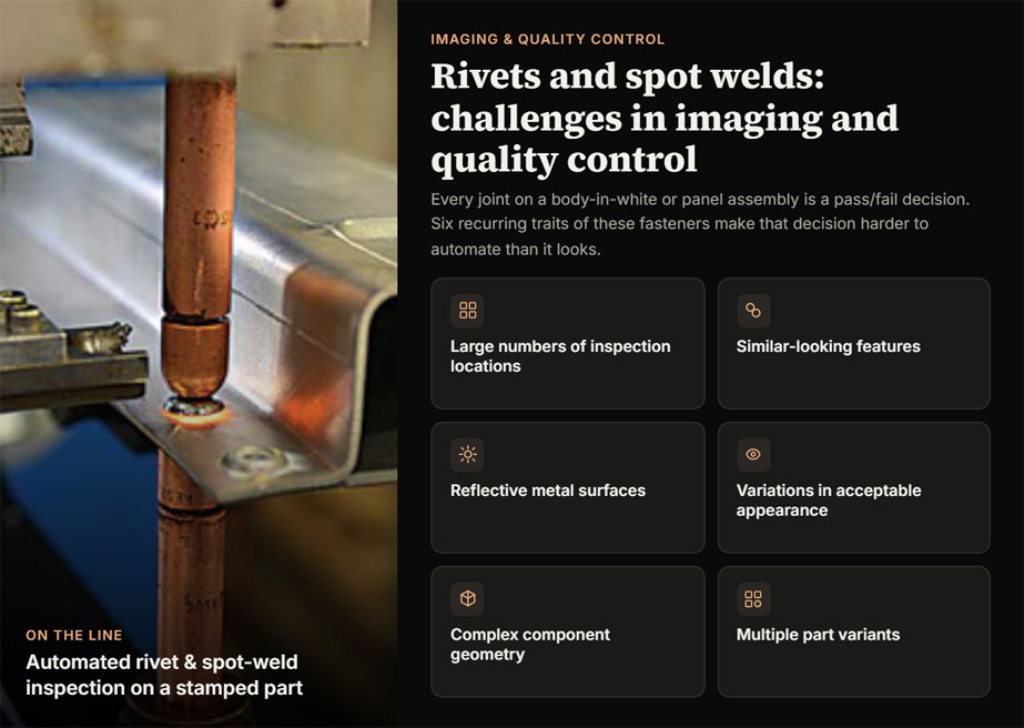
Large numbers of inspection locations
A component may contain hundreds or thousands of rivets and spot welds. Each location must be checked against the correct design or inspection map. A feature can be missing even when all surrounding locations are correct, so the system must verify every required position rather than relying only on an overall appearance check.
Similar-looking features
Rivets, spot welds, holes, surface marks, sealant, and reflections may have similar shapes in an image. The AI must distinguish an actual fastening or joining feature from an empty hole, tooling mark, stain, weld spatter, or other visual pattern.
Reflective metal surfaces
Bare aluminium, coated steel, stainless steel, painted panels, and metallic fasteners can create glare. Reflections may hide a small crack, distort the apparent edge of a rivet, or make a spot weld appear larger or smaller.
Variations in acceptable appearance
Acceptable rivets and spot welds do not always look identical. Their appearance can vary because of material, coating, surface texture, electrode condition, tooling, sealant, lighting angle, part geometry, and normal process variation. The inspection system must recognize acceptable variation without overlooking genuine defects.
Complex component geometry
Rivets and spot welds may be distributed across flat, curved, angled, vertical, or recessed surfaces. One fixed camera cannot always image every location at the required angle and resolution.
Multiple part variants
Different product models may have different rivet patterns, spot-weld maps, feature counts, surface geometries, materials, acceptance limits, and inspection regions. The correct inspection configuration must be applied automatically to each variant.
How Intelgic Addresses the Challenges
Intelgic designs the imaging and automation architecture around the component geometry, joining process, defect requirements, production rate, and available inspection time.
The component is divided into multiple inspection regions. For each region, Certainty defines the camera position, lighting condition, expected feature locations, AI model, and inspection limits.
Controlled imaging
The inspection station uses controlled illumination to reduce the influence of changing ambient factory light. Depending on the surface and defect type, Intelgic may use:
The inspection may take place inside a dark or optically enclosed cell when the surface is highly reflective or the required defects are particularly small.
Multi-light image capture
One lighting direction may reveal a scratch or raised edge while another provides a better view of weld shape or surface indentation. Certainty can capture several images of the same region under different lighting conditions. Intelgic's AI analyzes the complementary images to separate actual physical features from glare, shadows, and reflections.
Robotic camera positioning
A robot or cobot moves the camera and lighting assembly to each inspection region. The robot maintains the required:
For large components, the robot may be installed on a linear track. Multiple robots can also be used where one robot cannot provide the necessary coverage or cycle time.
Part localization
Reference cameras, laser sensors, or 3D sensors determine the component's actual position. Certainty can align the stored inspection map with the physical part and compensate for permitted fixture or loading variation. This prevents normal part-position changes from being mistaken for incorrectly positioned rivets or welds.
Inspection Configurations
Robot-mounted camera
A robot carries the camera and lighting system around a stationary component. This configuration is suitable for:
Robot moves the component
For smaller parts, a robot can pick up the component and present its different surfaces to stationary cameras and lights. This can provide repeatable imaging while keeping the optical equipment fixed.
Fixed multi-camera station
Several cameras capture different component surfaces simultaneously or in a short sequence. This approach can support high-speed inspection when part position and geometry are consistent.
How the Inspection Process Works
Presence Inspection
Presence inspection verifies that every required joining feature exists. The system compares detected rivets and welds with a digital reference map derived from engineering data, CAD information, inspection plans, approved reference components, or manually configured feature coordinates.
Possible presence results include:
The system can also count the total number of rivets and spot welds and compare the result with the expected count.
Counting alone is not sufficient. A component could contain the correct total number but still have one missing feature and one unexpected feature elsewhere. Location-by-location verification provides a more reliable result.
Position Inspection
Position inspection verifies whether the detected feature falls within the specified tolerance zone. The software can measure:
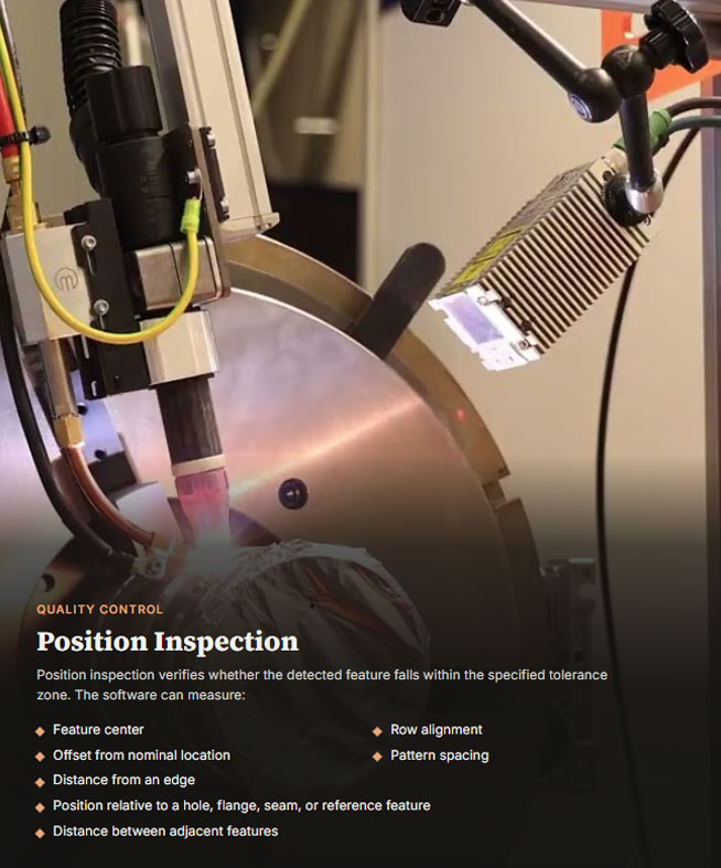
For spot welds, an incorrectly located weld may fall too close to an edge or outside the intended sheet overlap. For rivets, the system may detect an off-center or misaligned installation relative to the expected hole or fastener pattern.
Measurement accuracy depends on camera calibration, image resolution, lens distortion, part localization, viewing angle, and surface geometry.
Quality Inspection
Quality inspection evaluates the visible condition of the rivet or spot weld. Because rivets and spot welds have different defect mechanisms, Certainty can apply a separate AI model and inspection logic to each feature type.
The system can also use location-specific criteria. A critical region may have different inspection requirements from a noncritical or cosmetic area.
State-of-the-Art AI for Defect Detection
Traditional machine vision works well for features that can be evaluated using fixed limits for size, position, circularity, contrast, or color. Rivet and spot-weld defects are often irregular, and their appearance can also change with material, coating, lighting, sealant, and manufacturing variation.
Intelgic's AI learns these visual patterns from representative images of acceptable and defective components. The AI may perform:
Feature detection
Finds each rivet or spot weld and associates it with the correct expected location.
Classification
Determines whether the feature is acceptable or belongs to a trained defect category.
Segmentation
Identifies the pixels associated with the feature or defect, allowing its visible dimensions and area to be calculated.
Anomaly detection
Flags a location that differs from validated examples of acceptable features, including unusual conditions not included in a predefined defect class.
Multi-image analysis
Compares images captured under different lighting conditions to distinguish defects from reflections and surface variation.
Confidence evaluation
Assigns a confidence score that can be used to route uncertain results for qualified review.
Combining AI with Rule-Based Vision and 3D Measurement
The most effective inspection architecture may combine several approaches. For example, for a rivet:
For a spot weld:
This hybrid approach uses AI for complex defect appearance and conventional metrology for calibrated measurements.
Certainty Inspection Platform
Certainty manages the complete rivet and spot-weld inspection workflow. It coordinates:
Recipe Management for Different Variants
Certainty can maintain an individual inspection recipe for every component variant. The correct recipe can be loaded automatically using the part identity or manufacturing order. A recipe may control:
Automatic recipe selection allows one inspection cell to process components with different dimensions, patterns, materials, and acceptance requirements.
Integration with Existing Systems
Certainty can be integrated with existing factory automation and manufacturing software.
PLC integration
The platform can exchange:
MES integration
MES connectivity can support:
Additional connectivity
Certainty can also connect with:
Cloud-Based Quality Inspection Analytics
Inspection data can be transferred to a secure cloud analytics environment, subject to the manufacturer's cybersecurity and data-governance policies.
Quality dashboards
Quality dashboards may display:
Defect heat maps
Aggregated results can show where rivet or spot-weld defects occur most frequently on the component. Repeated defects in one area may indicate issues involving:
Image-level traceability
Authorized users can review original images, annotated defects, measured positions, AI confidence, inspection recipes, and production history.
Multi-site quality monitoring
Cloud analytics can provide authorized teams with consolidated quality information across production lines, plants, and suppliers. An on-premises or hybrid architecture can be used where image or production-data storage in the cloud is restricted.
Digital Inspection Records
For each component, Certainty can record:
Rivet Defects That Can Be Detected
Depending on the validated imaging system, Intelgic's AI can inspect for visible conditions such as:
Missing rivets
The expected location contains no rivet or contains an empty hole.
Damaged rivet heads
Visible damage may include:
Incorrect rivet type
The visible head shape, dimensions, color, marking, or other feature differs from the expected rivet.
Raised or recessed rivets
A rivet may sit above or below the surrounding surface. Appearance-based inspection can identify an abnormal condition, while calibrated 3D sensing may be required for precise flushness measurement.
Tilted or misaligned rivets
The head may appear asymmetrical or incorrectly aligned with the panel surface.
Cracks around rivets
The system may detect visible cracks extending from the fastener location when the crack width, surface finish, lighting, and image resolution provide sufficient contrast.
Sealant anomalies
Visible conditions may include missing, excessive, discontinuous, or contaminated sealant around a rivet.
Spot-Weld Defects That Can Be Detected
Depending on the application, surface imaging can inspect for:
Missing spot welds
The expected location contains no visible weld impression.
Incorrectly positioned welds
The weld is offset from its specified coordinate or falls outside the permitted joining area.
Expulsion and spatter
Excessive material ejection may produce visible spatter, pits, or irregular surface conditions.
Burn-through
Excessive heat may create a hole or severe local surface damage.
Excessive indentation
The electrode impression appears deeper or more severe than the approved visible condition. Quantitative depth generally requires 3D measurement.
Irregular weld impression
The weld mark may have an abnormal shape, size, edge, or surface texture.
Visible cracking
Surface-breaking cracks may be detected when the imaging conditions provide adequate contrast.
Electrode-related abnormalities
Changes in the weld impression may indicate electrode wear, contamination, misalignment, or other process variation.
Surface imaging does not directly determine internal weld fusion, nugget size, internal rivet formation, or joint strength. Where these properties must be verified, another validated method may be required alongside visual inspection.
Looking to automate rivet and spot-weld inspection? Contact Intelgic to discuss a robotic Visual AI system for presence, position, and visible quality inspection powered by the Certainty platform.
Frequently Asked Questions
Can one system inspect both rivets and spot welds? +
Yes. Certainty can apply separate inspection logic and AI models to rivets and spot welds while managing both within the same component recipe and inspection report.
Can AI detect a missing rivet or spot weld? +
Yes. The AI compares every expected location with the captured image and identifies missing, additional, or obstructed features.
Can the system measure feature position? +
Yes. A calibrated vision system can calculate the feature center and compare it with the nominal coordinate and permitted tolerance zone.
Can AI inspect rivet and weld quality? +
AI can inspect defined visible conditions such as damaged rivet heads, abnormal seating, weld expulsion, burn-through, irregular impressions, and visible cracks.
Can visual inspection verify the internal strength of a joint? +
No. Surface imaging does not directly determine internal weld fusion, nugget size, internal rivet formation, or joint strength. Other validated methods may be required.
Can one inspection cell handle multiple part variants? +
Yes. Certainty can store variant-specific rivet and weld maps, robot paths, camera settings, lighting sequences, AI models, and inspection limits.
Can defects be displayed on a component map? +
Yes. Certainty can link each result to its physical location and display missing, misplaced, or damaged features on a digital defect map.
Can Certainty integrate with an existing PLC and MES? +
Yes. Certainty can exchange part identity, recipe, machine status, inspection results, alarms, traceability, and rework information with existing systems.
Are inspection results available through cloud dashboards? +
Yes. Subject to the manufacturer's data policies, dashboards can display defect trends, heat maps, pass/fail rates, images, feature-level results, and production-quality metrics.