Identify Parts Without Barcodes Using Machine Vision, 3D Laser Scanning, and CAD Matching
Manufacturers, warehouses, maintenance teams, and assembly lines regularly handle parts without barcodes, labels, serial numbers, or readable identification marks.
An experienced operator may recognize a familiar component, but identifying thousands of visually similar parts manually is slow and prone to error. The challenge becomes greater when components are randomly oriented, stored outside their original packaging, covered with oil or dust, or separated from their production records.
Intelgic solves this problem using machine vision cameras, 3D laser sensors, AI, and CAD-model matching.
The system captures the part's visual and three-dimensional characteristics, compares them with approved design files or CAD models, identifies the best match, and provides the corresponding part number as its output.
The part itself becomes its identifier.
The Challenge of Unmarked Parts
Barcodes, QR codes, RFID tags, and printed part numbers provide reliable identification when they are available and readable. However, many industrial components do not carry an identifier.
Common examples include:
Identification labels may be missing because the part is too small, the surface is unsuitable for printing, the identifier was removed during processing, or the component was never individually marked. Labels can also become damaged, contaminated, detached, or unreadable.
When identification depends only on operator knowledge, manufacturers may experience:
Intelgic automates identification by examining the physical part instead of relying on an attached code.
What Is Vision- and CAD-Based Part Identification?
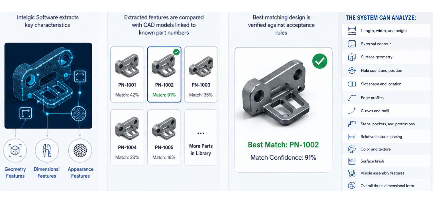
Vision- and CAD-based part identification uses the component's observable geometry and appearance as a digital fingerprint. Industrial cameras capture visible features, while 3D laser sensors measure the component's shape and depth. Intelgic's software extracts relevant characteristics and compares them with a library of design files linked to known part numbers.
The system can analyze:
Once the best matching design is identified and verified against the configured acceptance rules, the system outputs information such as:
How Intelgic's Part Identification System Works
The identification process connects physical imaging with digital engineering data.
The component is placed within the inspection area using a suitable presentation method, such as a conveyor, fixture, turntable, transparent inspection surface, robot or cobot, tray, scanning booth, manual loading station, or bin-picking cell.
Consistent presentation can improve speed and accuracy, but Intelgic can also design systems for parts arriving in different positions and orientations. The presentation method depends on the part's size, weight, geometry, production flow, and required inspection coverage.
Industrial cameras acquire high-resolution images of the component. Depending on the application, Intelgic may use area-scan cameras, line-scan cameras, high-resolution monochrome cameras, color cameras, multiple camera viewpoints, telecentric imaging, robot-mounted cameras, or backlit contour imaging.
Lighting is engineered to create consistent images and make identifying features visible. Backlighting may reveal a precise silhouette, while diffused or directional lighting can reveal surface details.
A 2D image may not distinguish parts that have the same outline but different heights, pockets, bends, steps, or surface profiles. Intelgic can add 3D laser sensors to capture height, depth, surface profile, curvature, volume, bends and formed regions, raised or recessed features, hole and cavity depth, and three-dimensional orientation.
As the laser scans across the part, the system generates a 3D representation, commonly a height map, profile, or point cloud. This geometric information allows the system to distinguish components whose differences are invisible from a top-view image.
Before matching can begin, the system identifies which image pixels or 3D points belong to the component.
The resulting data represents the component without irrelevant surroundings.
Intelgic's software converts the captured data into measurable features.
Features that remain reliable under rotation or minor production variation are especially valuable for automatic identification.
The system compares the measured characteristics with a database of known components. Each database record may contain a CAD model, 2D engineering drawing, reference images, part number, part description, product family, revision, nominal dimensions, manufacturing tolerances, material, and approved visual variations.
Basic features such as overall dimensions and hole count can quickly eliminate impossible candidates. For example, if the scanned component has five holes and a particular length range, designs with different hole counts or incompatible dimensions can be excluded immediately.
The captured part may be rotated, translated, tilted, or flipped relative to its CAD model. Intelgic's matching software aligns the measured data with candidate designs. This process, often called registration, finds the position and orientation that produce the closest geometric agreement.
For a 3D comparison, the system evaluates how closely the scanned surface agrees with the nominal CAD geometry after alignment.
Intelgic can combine AI-based recognition with geometric CAD comparison. AI helps classify the component family and understand complex visual patterns. Geometric matching verifies whether the measured shape and features agree with a specific design.
This hybrid approach offers the flexibility of AI together with the explainability of engineering measurements.
When the match satisfies the required confidence and geometric criteria, Intelgic's system returns the associated part number.
Part description: Right-hand mounting bracket
CAD revision: R2
Match confidence: 99.1%
Orientation: Face up, rotated 32°
Result: Identified
Next destination: Assembly Line 4
The result can be displayed to an operator, sent to a PLC, used to guide a robot, recorded in MES or ERP, or transmitted to a warehouse-management system.
A responsible identification system should not force every component into a known category. If two parts are too similar or the scan quality is insufficient, the system can return unknown part, multiple possible matches, low-confidence identification, incorrect presentation, additional view required, or manual review required.
The component can then be diverted to a review station or imaged from another angle. This prevents an uncertain match from becoming an incorrect part-number assignment.
Why Combine 2D Cameras and 3D Lasers?
Two-dimensional imaging and three-dimensional sensing provide complementary information.
Capture contour and visual appearance.
Detect holes, slots, color, and markings.
Support high-speed image acquisition.
Read visible text and codes when present.
Compare the part with 2D drawings or CAD projections.
Capture height and depth.
Detect bends, steps, pockets, and surface form.
Provide geometric measurements.
Work independently of part color in many applications.
Compare point clouds with 3D CAD models.
A camera may distinguish two parts by their hole patterns. A 3D laser may distinguish them by their bend height or recessed geometry. Combining both technologies gives the system a more complete representation of the component.
Matching a Physical Part with a CAD Design
A CAD model represents the intended component, while the imaging system captures the manufactured component. These two datasets are not identical.

The matching system must allow acceptable production variation without confusing different part numbers. Intelgic configures match thresholds using real parts, engineering tolerances, and the minimum differences between similar components.
CAD data can provide more than a geometric reference. It can also help build the AI identification system.
Virtual images of each CAD model can be rendered under different orientations, viewing angles, distances, lighting directions, backgrounds, and occlusion levels. These synthetic examples can support AI training before large numbers of production images are available.
Actual production images remain important because real surfaces, reflections, manufacturing variation, contamination, and camera conditions differ from ideal CAD renders. Intelgic can combine synthetic and real data to develop a robust model.
A full 3D CAD model is not always available. Some applications have only 2D drawings or digital profiles. The system may still identify parts using outer contour, dimensions, hole pattern, slot location, edge shape, feature spacing, and drawing projections.
This approach is particularly useful for flat components such as laser-cut parts, gaskets, sheet-metal blanks, washers, flat stampings, printed components, seals, and machined plates.
For parts with important height or depth differences, a 3D design model or additional reference data may be necessary.
Handling Random Orientation and Nearly Identical Parts
The system can identify parts even when they are rotated, mirrored, face up or face down, tilted, presented at different positions, or viewed from different angles.
Orientation-independent recognition is achieved through image normalization, pose estimation, multi-view imaging, AI training, and CAD registration.
When only one surface is visible, some components may require the system to flip or rotate the part for additional imaging. A robot, turntable, or multi-camera arrangement can provide the additional views.
Many industrial components share the same general shape and differ by only one small feature: one additional hole, different hole spacing, different thread size, a small change in length, left-hand and right-hand geometry, different bend angle, a shifted slot, a raised instead of recessed feature, different connector position, or different CAD revision.
Intelgic identifies these components by focusing on the features that distinguish one design from another.
The required image resolution and 3D accuracy are determined by the smallest difference the system must identify.
Can the System Identify a CAD Revision?
Revision identification is possible when the revisions create an observable difference that the cameras or 3D sensors can measure. Examples include added or removed holes, changed dimensions, modified edge profiles, different bend geometry, new pockets or slots, and relocated features.
If two revisions are physically identical in all observable regions, no vision system can reliably distinguish them without another source of information. In such cases, identification may require production records, material data, embedded tags, packaging information, or process traceability.
Part Identification Versus Dimensional Inspection
Part identification determines which known design best matches the component. Dimensional inspection determines whether the component conforms to that design. The two functions can be combined, but they serve different purposes.
After identifying a component, Intelgic's system may perform selected quality checks, such as:
The output can therefore include both the part number and an inspection result.
Applications in Manufacturing, Warehousing, and Spare Parts
The system identifies a component before assembly and confirms that it matches the required work order or BOM.
A robot identifies the part, selects the correct program or fixture, and loads it into a CNC machine, press, inspection station, or assembly cell.
Unmarked components are identified and placed into dedicated bins according to part number.
The system verifies and collects the correct components for an assembly kit.
Parts moving between operations can be identified without applying temporary labels at every stage.
The system confirms the physical identity of a manufactured component before packaging or shipment.
Applications in Warehousing and Spare Parts
Warehouse and maintenance operations frequently contain components whose packaging or labels have been lost. Intelgic's system can help identify unmarked inventory, returned components, spare parts, legacy parts, maintenance components, parts removed during disassembly, mixed stock, and items awaiting put-away.
The identified part number can be used to retrieve inventory location, product description, compatible equipment, stock quantity, purchase history, supplier information, assembly relationship, and replacement requirements.
Robotic Identification and Sorting
The cell can therefore identify, inspect, pick, sort, count, and route unmarked components automatically.
Integration with Engineering and Factory Systems
Intelgic's identification platform can integrate with:
Integration keeps the CAD library, part-number information, revisions, work orders, and physical identification results connected.
A reliable system requires a controlled relationship between design files and part numbers. Each record should contain appropriate information such as unique part number, part name, CAD model or drawing, revision, nominal dimensions, manufacturing tolerances, part family, material, reference images, distinguishing features, and active or obsolete status.
When a new design is introduced, it can be added to the library and evaluated against existing models to determine whether the system can distinguish it reliably.
Each identification event can create a digital record containing captured image, 3D scan, identified part number, candidate matches, match confidence, CAD revision, dimensions, position and orientation, date and time, workstation, operator or robot, destination, inspection result, and manual-review status.
Dashboards can show parts identified by type, unknown-part frequency, low-confidence results, identification rate, match confidence trends, mixed-part occurrences, parts sorted per hour, review outcomes, and results by batch or shift.
This data helps manufacturers improve inventory accuracy, production control, and system performance.
Benefits of Identifying Parts Without Barcodes
Intelgic's solution can help manufacturers achieve:
Factors That Determine Identification Performance
System performance depends on number of CAD models, similarity between parts, smallest distinguishing feature, camera and 3D-sensor resolution, part size, surface reflectivity, product orientation, visible surface area, presence of occlusion, manufacturing tolerance, scanning speed, required confidence, and availability and quality of design data.
Highly reflective, transparent, flexible, heavily contaminated, or mutually occluded parts may require specialized optical arrangements or controlled presentation. Representative physical samples and design files should be evaluated before the final system architecture is selected.
An Application-Specific Identification Solution
No single sensor or matching method is ideal for every component. Intelgic designs custom systems that may combine:
The solution is engineered around the components, distinguishing features, identification speed, and production environment.
Let the Part Identify Itself
A component does not always need a barcode, label, or readable marking to be identified. Its dimensions, shape, surface geometry, hole pattern, edges, and other physical features already contain valuable identity information.
Intelgic uses machine vision cameras and 3D laser sensors to capture that information. AI and geometric matching compare the physical part with approved CAD models or design files. Once the best match is verified, the system returns the associated part number and sends it to the required manufacturing, warehouse, or robotic process.
With Intelgic, the physical component becomes the identifier, connecting real-world parts with digital engineering data automatically.
Part Identification · CAD Matching
Frequently Asked Questions
Yes. A part can be identified from its dimensions, contour, hole pattern, surface geometry, and other physical features. Intelgic compares these features with known design files and returns the corresponding part number.
Machine vision cameras and 3D laser sensors capture images, profiles, or point clouds. The software extracts geometric features, retrieves possible CAD candidates, aligns the scan with each candidate, and calculates which design provides the best verified match.
Cameras capture contours, holes, color, texture, and other visual details. A 3D laser captures height, depth, bends, pockets, and surface geometry. Combining them improves identification when parts have similar 2D appearances.
Yes. Pose-estimation and CAD-registration techniques can align rotated, translated, tilted, or flipped parts with their design models. Some components may require multiple views.
It can distinguish revisions when they contain a measurable physical difference. If two revisions are physically identical in all visible and measurable areas, additional production or traceability data will be necessary.
The system can return multiple candidates or flag the result for manual review. It should not assign a part number when the available sensor data cannot reliably distinguish the designs.
Yes. After identification and pose estimation, a robot or cobot can pick the part and place it into a dedicated bin, assembly fixture, machine, or packaging location.
Yes. After determining the part number, the system can apply its inspection recipe and check selected dimensions, feature presence, deformation, or visible defects.