Is Every Manufactured Part Matching Its Engineering Drawing?
In metal fabrication, stamping, machining, and wooden panel manufacturing, even a small dimensional error can lead to assembly failures, misalignment, rework, or product rejection.
A hole positioned just outside its specified tolerance can prevent components from fitting together. An incorrect slot dimension, missing cutout, or warped panel can make an otherwise finished part unusable.
Manufacturers traditionally rely on manual gauges, calipers, coordinate measuring machines (CMMs), and periodic sampling to verify dimensional accuracy. While these methods remain important, they can be time-consuming when every part contains multiple measurement checkpoints.
Intelgic offers an automated 3D laser-based dimensional inspection solution that scans metal and wooden components, measures critical geometric features, and compares the actual part dimensions with the original engineering design.
The solution uses a 3D laser profiler mounted on a robotic motion system. Once the part is loaded into the inspection station, the sensor moves across the component, captures its three-dimensional geometry, and automatically evaluates each measurement against predefined tolerances. The system communicates with existing manufacturing software to retrieve the part’s design file and inspection specifications.
Every part receives an automated Good or NG (Not Good) decision, supported by a comprehensive dimensional quality report.
Why Manufacturers Need Automated Dimensional Inspection
Dimensional accuracy is critical to downstream manufacturing operations.
In sheet metal fabrication, incorrectly positioned holes can cause fastening and welding alignment problems. In wooden panel manufacturing, inaccurate drilling positions or cutout dimensions can prevent proper furniture assembly. Common inspection challenges include:
Length, width, thickness, or feature sizes outside tolerance.
Drilled or stamped holes that do not align with the engineering drawing.
Oversized or undersized holes that affect fastening.
Incorrect drilling or punching operations.
Incorrect profiles, slots, notches, or cutout shapes.
Bending, warpage, and flatness deviations.
Multiple gauges and repetitive measurements slow down quality control.
Measurement results may not be digitally linked to the original design and part identifier.
Intelgic’s automated inspection system addresses these challenges through non-contact 3D measurement and direct comparison against the approved part design.
How Intelgic’s Robotic 3D Laser Measurement System Works
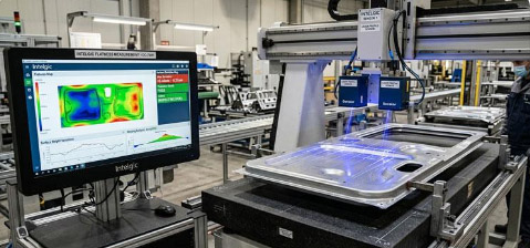
Intelgic combines a 3D laser profiler, robotic motion system, dimensional measurement software, and manufacturing system integration into a single automated inspection station.
- 01Retrieve Part Design
Get part ID, CAD or drawing specifications, and tolerances from the existing system
- 02Load Part
Position the component in the inspection station
- 03Perform 3D Laser Scan
Robotic motion system moves the profiler across the part
- 04Measure Dimensions
Extract holes, edges, contours, and surface geometry
- 05Compare with Design
Evaluate actual measurements against nominal dimensions and tolerances
- 06Generate Quality Result
Display Good or NG and save the inspection report
Automatic Retrieval of Part Design and Inspection Requirements
At the beginning of the inspection process, the system identifies the part using:
Intelgic’s software communicates with the existing ERP, MES, or engineering system through an API to retrieve the relevant design information. This can include:
Where drawings are supplied as PDF files, the measurement features and tolerances must be extracted and validated before they are used for automated decisions.
Automated 3D Scanning Using Robotic Motion
The part is loaded onto the inspection table or holding fixture. A 3D laser profiler mounted on a robotic linear motion system moves across the component, capturing a continuous sequence of laser profiles. These profiles are combined into a 3D representation of the inspected surface.
Illustrative scan. The laser line sweeps across the part and each captured profile is stacked into a calibrated 3D surface.
The scanning system captures the geometry of visible features such as:
For large parts, the motion system can scan multiple regions to cover the full inspection area.
Measurement, CAD Verification, and Good / NG Classification
Automatic Geometric Measurement
Intelgic’s measurement software processes the 3D scan and identifies predefined geometric features. It calculates dimensions using calibrated spatial coordinates rather than relying solely on a conventional 2D image.
The resulting measurements can be compared with the actual design specifications and tolerance limits.
CAD-Based Part Verification
The scanned geometry is aligned with the approved engineering design using defined reference points, edges, holes, or datum features. The software then calculates the deviation between the manufactured part and nominal design geometry.
For example, if a hole is designed at X = 150 mm and Y = 75 mm, the system measures the actual center location and evaluates its deviation using the specified positional tolerance.
Illustrative example. The measured hole centre (red) is compared with the nominal position (blue); the result passes when it falls inside the positional tolerance zone.
Automatic Good / NG Classification
After all configured checkpoints are evaluated, the system generates an inspection decision.
All required measured features are within their acceptance limits.
One or more features exceed the defined tolerances.
A required measurement could not be verified reliably.
The result can be displayed at the inspection station and communicated to the existing production system.
What Can Intelgic’s 3D Laser Measurement System Inspect?
Length and Width Measurement
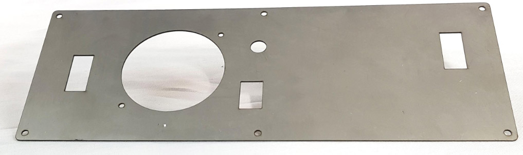
The system measures the overall length and width of metal plates, stamped components, wooden panels, and other flat or formed parts. It can identify dimensional variations caused by cutting, stamping, machining, or manufacturing deformation.
Applications
Hole Diameter and Hole Position Measurement
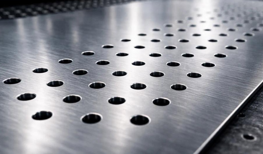
Hole measurement is one of the most valuable applications of laser-based dimensional inspection. Intelgic’s software identifies visible hole boundaries and calculates the hole center and opening diameter. It can verify:
Prevents assembly problems caused by misplaced or incorrectly sized holes.
For deep holes, internal bore dimensions, or obstructed features, additional scanning arrangements or complementary measurement sensors may be needed.
Stamping Shapes, Cutouts, Flatness, and Warpage
Stamping Shape and Cutout Verification
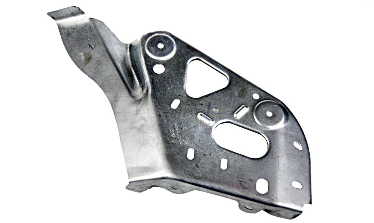
Stamped metal parts frequently contain complex outlines, slots, notches, bends, and irregular cutouts. Intelgic compares the measured contour with the approved design geometry. The system can detect:
Helps manufacturers identify stamping and cutting errors before parts reach assembly.
Surface Flatness, Warpage, and Deformation
A component may have the correct length, width, and hole dimensions but still fail because the surface is bent or warped. Intelgic’s 3D laser profiler captures surface height variations and evaluates them against the specified geometric tolerance.
Measurements can include:
Supports reliable assembly fit and improves control over stamping, machining, and panel production.
Additional Dimensional Inspection Checkpoints
Beyond length, holes, shapes, and flatness, the system can be configured to evaluate a wide set of geometric checkpoints on every part.
All measurements depend on the selected profiler’s range and resolution, scan accessibility, fixture calibration, and required tolerance.
Automated Inspection of Metal and Wooden Components
Inspect steel and aluminum plates, brackets, sheet metal stampings, machined components, and fabricated parts for dimensional accuracy, hole geometry, cutout profiles, and deformation.
Measure MDF, plywood, engineered wood, and furniture panels for length, width, drilling positions, hole dimensions, grooves, slots, edge profiles, and warpage.
The same inspection architecture can support different material types by adjusting sensor selection, scanning recipes, and measurement requirements. Intelgic has also documented applications for both metal stamping verification and wooden panel and flatness inspection.
Real-Time CAD Comparison and Automatic Quality Decisions
One of the key advantages of Intelgic’s inspection solution is its ability to compare the manufactured part directly with its approved engineering design.
Rather than manually entering every measurement, the system can receive validated design information and configured tolerance specifications through integration with existing software. It identifies the expected features, measures their actual geometry, and evaluates each result against the acceptance criteria.
Example: Automated Dimensional Quality Report
| Checkpoint | Actual | Specification | Result |
|---|---|---|---|
| Length | 550.12 | 550 ± 0.50 | Good |
| Width | 549.88 | 550 ± 0.50 | Good |
| Hole H1 diameter | 10.03 | 10 ± 0.10 | Good |
| Hole H2 diameter | 9.98 | 10 ± 0.10 | Good |
| Hole H3 X position | 125.42 | 125 ± 0.20 | NG |
| Slot width | 20.04 | 20 ± 0.10 | Good |
| Flatness | 0.18 | ≤ 0.30 | Good |
All dimensions in millimeters. Illustrative nominal values and tolerances, not actual customer measurements.
Hole H3 is outside its specified X-position tolerance. The part is flagged for review or rejection.
The report can also contain 3D deviation maps, feature coordinates, inspection timestamps, and detailed pass/fail results for every configured checkpoint.
For engineering drawings using geometric dimensioning and tolerancing (GD&T), measurements must be evaluated with the correct datum reference frames and tolerance definitions. ISO 1101 provides the standardized language for geometric specifications such as form, orientation, and location tolerances.
Flexible Inspection Recipes for Different Part Designs
Manufacturers frequently produce hundreds of part variants with different dimensions and geometries. Intelgic’s system supports configurable inspection recipes that define:
When a new part is loaded, the system can retrieve the appropriate design and activate its inspection recipe.
This reduces repeated manual setup and allows a single inspection cell to support multiple compatible part configurations.
Integration with Existing Manufacturing Systems
Intelgic’s inspection system can communicate with ERP, MES, CAD management, and quality management applications.
For example, a manufacturing system can send the day’s production list containing part IDs, design references, and inspection requirements. When a part is loaded, Intelgic’s system identifies it, retrieves the appropriate design specifications, performs the 3D scan, and sends the inspection result back to the existing system.
- →Daily production list
- →Part IDs & design references
- →Inspection requirements
- ←Good / NG result per part
- ←Measured values & deviations
- ←Digital inspection report
The integration can support:
This creates a connected inspection workflow without requiring operators to manually enter every measurement.
Why Use a Robotic 3D Laser Profiler Instead of Manual Inspection?
Manual gauges and CMMs remain valuable tools. Automated 3D laser inspection changes how many checkpoints can be verified on every part, and how consistently.
Business Benefits of Automated 3D Dimensional Inspection
Quantitative 3D dimensions compared with engineering tolerances
Reduce repetitive manual measurement tasks
Apply the same acceptance criteria to every part
Compare manufactured features with approved design geometry
Support different designs through configurable recipes
Maintain traceable records of dimensional quality
The system can help manufacturers reduce inspection time, identify dimensional errors earlier, and prevent out-of-tolerance components from progressing to downstream assembly.
What Determines Measurement Accuracy?
The achievable measurement accuracy depends on several factors:
Intelgic selects the laser profiler and motion configuration based on the part dimensions, minimum feature sizes, required tolerances, and target inspection cycle time.
For demanding measurement applications, system capability should be validated using suitable reference parts and repeatability studies before production release.
Applications Across Manufacturing Industries
Plate dimensions, holes, slots, outer contours
Stamped brackets, panels, mounting features
MDF panels, drilling positions, routed shapes
Steel plates, fabricated components, flanges
Metal covers, enclosures, mounting holes
Structural brackets and cut metal parts
Accessible machined profiles, holes, and edges
Metal panels, cabinet components, cutouts
Why Choose Intelgic for 3D Laser Dimensional Inspection?
Intelgic delivers integrated industrial measurement and quality assurance solutions combining precision hardware, intelligent software, and manufacturing automation. Our solution can include:
The system can be configured for metal plates, stamped parts, wooden panels, and other suitable manufactured components.
From Engineering Design to Automated Quality Assurance
Manufacturing quality begins with ensuring that every component matches its engineering specifications. Incorrect hole positions, dimensional variations, missing cutouts, or deformed shapes can create expensive downstream assembly problems.
Intelgic’s robotic 3D laser measurement system automatically scans manufactured parts, measures critical dimensions, compares them with approved engineering designs, and generates Good or NG decisions based on defined tolerances.
By connecting the inspection station directly with manufacturing software, Intelgic helps manufacturers establish a more automated, consistent, and traceable quality control process.
Frequently Asked Questions
What is automated 3D laser dimensional inspection?
It is a non-contact inspection method that uses a laser profiler to capture three-dimensional part geometry and automatically measure dimensions against predefined specifications.
Can the system measure length and width?
Yes. Intelgic’s system can measure the overall length and width of components within the configured scanning range.
Can it measure hole position and diameter?
Yes. The system can identify accessible hole boundaries and calculate hole diameter, center coordinates, spacing, and position relative to defined references.
Can the system detect missing or incorrectly stamped holes?
Yes. It can compare the detected holes against the expected design and flag missing, extra, incorrectly sized, or misplaced holes.
Can it measure complex stamping shapes?
Yes. The 3D laser scanner can capture visible contours, slots, cutouts, notches, and formed features and compare them with the nominal geometry.
Can Intelgic inspect wooden panels?
Yes. The system can inspect wooden panels, MDF boards, plywood, and other suitable flat or formed components for dimensional accuracy, holes, grooves, and warpage.
How does the system compare measurements with CAD files?
The software retrieves or imports approved engineering specifications, aligns scanned geometry to defined datums, and evaluates measured features against their nominal dimensions and tolerances.
Can it read PDF engineering drawings?
The system can be integrated with workflows that import or extract specifications from PDF drawings. Extracted dimensions and tolerances must be verified before they are used for automatic acceptance decisions.
What does Good / NG mean in dimensional inspection?
Good means all required measurements satisfy the configured acceptance criteria. NG means at least one required feature is outside tolerance. Uncertain or incomplete measurements can be flagged for review.
Can one system inspect different parts?
Yes. Multiple part designs can be supported using configurable scanning and measurement recipes, provided the parts are compatible with the inspection cell’s size and sensor capability.
Does the system require a robotic arm?
Not necessarily. A robotic linear motion or gantry system is often suitable for scanning flat metal and wooden components. More complex geometries may benefit from additional motion axes.
Can the system measure thickness and hole depth?
Yes, when the necessary surfaces are accessible. Some thickness or deep-hole measurements may require additional sensor positions or complementary measurement devices.
Can the inspection report be sent to an existing MES or ERP?
Yes. Intelgic can integrate the inspection system with existing manufacturing software to exchange part information, specifications, and inspection results.
Can it replace a CMM?
It can automate many dimensional checks, but full replacement depends on the required uncertainty, feature accessibility, geometry, and applicable measurement standards.
What information does Intelgic need to design the inspection system?
Manufacturers should share part drawings or CAD files, maximum part dimensions, material types, measurement checkpoints, tolerance requirements, target inspection time, and production volume.