Inspect Every Tooth. Measure Every Critical Dimension. Ensure Gear Quality.
Gears are critical components in automotive transmissions, industrial gearboxes, robotics, aerospace systems, and heavy machinery. Their performance depends on precise tooth geometry, dimensional accuracy, and consistent manufacturing quality.
Even minor errors in tooth thickness, helix angle, pitch, or gear roundness can result in excessive noise, vibration, inefficient power transmission, premature wear, and mechanical failure.
Traditional gear inspection often relies on manual gauges, contact-based measuring instruments, coordinate measuring machines (CMMs), or dedicated gear measurement centers. While these systems can deliver excellent precision, they may require specialized setups, significant inspection time, or operator involvement.
Intelgic offers an automated 3D laser-based gear inspection solution that scans the gear as it rotates on a precision shaft, reconstructs its three-dimensional geometry, and measures critical dimensional checkpoints against predefined tolerances.
The system combines high-resolution 3D laser profilers, precision rotary motion, advanced measurement algorithms, and AI-based defect analysis to deliver comprehensive gear quality reports.
How Intelgic's 3D Laser Gear Inspection System Works
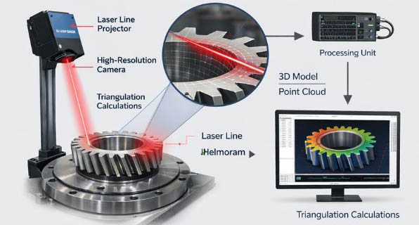
Intelgic uses laser triangulation technology to capture the precise three-dimensional geometry of gear teeth.
The gear is mounted on a precision rotating shaft or spindle, while one or more laser profile cameras scan its surface.
Step 1: Mount the Gear on a Precision Rotary Shaft
The operator or an automated loading system places the gear onto a calibrated fixture connected to a motorized rotary stage.
The fixture holds the gear securely while maintaining a defined reference axis for dimensional measurements.
Step 2: Rotate the Gear and Capture Laser Profiles
The 3D laser profiler projects a laser line across the gear teeth.
As the gear rotates, the sensor captures a continuous sequence of high-resolution profiles. A rotary encoder synchronizes the captured measurements with the angular position of the gear.
Step 3: Generate a 3D Digital Model
Intelgic's software combines the individual laser profiles into a dense 3D point cloud representing the scanned gear geometry.
This digital model contains the spatial information needed to measure gear teeth, tooth flanks, roots, and accessible reference surfaces.
Step 4: Measure Critical Gear Dimensions
Specialized metrology algorithms identify individual gear teeth and calculate dimensional parameters such as tooth thickness, tooth depth, outside diameter, pitch deviations, helix angle, and runout.
Measurements are compared with nominal gear geometry, CAD models, and engineering tolerances.
Step 5: Generate an Automated Quality Report
The system identifies out-of-tolerance dimensions, highlights deviations, and generates a comprehensive inspection report for each gear.
Reports can be linked to a part ID, serial number, production batch, or work order.
This non-contact scanning approach is supported by industrial gear metrology research demonstrating the use of line laser sensors to capture dense 3D tooth-surface information.
MDPI
+1
Comprehensive Gear Inspection: Critical Measurement Checkpoints
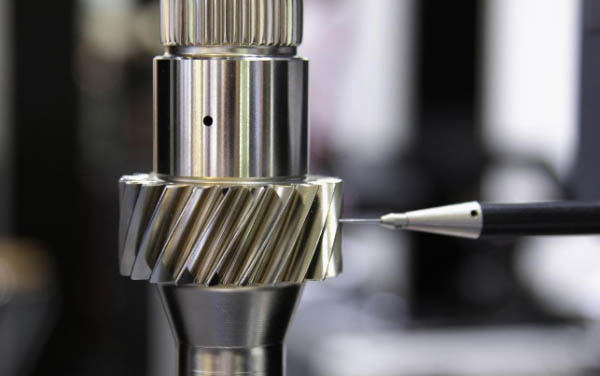
Intelgic's system can be configured to measure a broad range of gear dimensions and geometric errors.
The exact measurement capabilities depend on gear geometry, sensor resolution, scan access, fixture accuracy, and the required measurement uncertainty.
1. Gear Tooth Geometry and Dimensional Measurements
| Inspection Parameter | What the System Measures |
|---|---|
| Number of Teeth | Counts and verifies the total number of gear teeth |
| Outside Diameter (OD) | Diameter across the tooth tips |
| Root Diameter | Diameter across the tooth-root regions |
| Pitch Circle Diameter (PCD) | Reference diameter calculated from gear geometry and design parameters |
| Base Circle Diameter | Reference diameter associated with the involute tooth profile |
| Module | Gear tooth size parameter derived from pitch and reference geometry |
| Circular Pitch | Circumferential distance between corresponding points on adjacent teeth |
| Tooth Thickness | Tooth thickness at a defined reference diameter |
| Tooth Space Width | Spacing between adjacent teeth at a specified diameter |
| Tooth Depth | Total radial depth from tooth tip to root |
| Addendum | Tooth height above the reference pitch circle |
| Dedendum | Tooth depth below the reference pitch circle |
| Pressure Angle | Tooth flank geometry relative to the reference involute |
| Root Fillet Radius | Curvature of the transition between the tooth flank and root |
| Face Width | Axial width of the gear teeth |
Why it matters: Incorrect tooth dimensions can cause poor meshing, interference, excessive backlash, and accelerated wear.
2. Helical Gear and Tooth Flank Inspection
Helical gears require additional measurements because their teeth follow angled paths across the gear face.
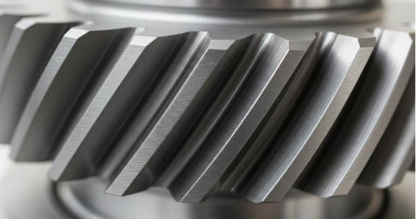
| Inspection Parameter | What It Verifies |
|---|---|
| Helix Angle | Angle of the helical tooth relative to the gear axis |
| Helix Direction | Left-hand or right-hand tooth orientation |
| Lead | Axial advance corresponding to one revolution of the tooth helix |
| Total Helix Deviation (Fβ) | Overall deviation of the measured tooth trace from its nominal geometry |
| Helix Slope Deviation (fHβ) | Deviation in the inclination of the tooth trace |
| Helix Form Deviation (ffβ) | Tooth trace form error after removing slope deviation |
| Total Profile Deviation (Fα) | Overall tooth flank profile error |
| Profile Slope Deviation (fHα) | Inclination error of the measured tooth profile |
| Profile Form Deviation (ffα) | Local tooth profile shape error |
| Tooth Lead Crowning | Intentional or unintended curvature along the face width |
| Profile Crowning / Tip Relief | Deviations from specified tooth flank modifications |
These profile and helix deviation categories are established in ISO 1328-1 for cylindrical gear flank tolerance classification.
ISO
+1
Why it matters: Helix and tooth profile errors can lead to uneven load distribution, gear noise, vibration, and premature tooth failure.
3. Pitch Accuracy, Runout, and Roundness Inspection
| Inspection Parameter | What It Verifies |
|---|---|
| Single Pitch Deviation (fpt) | Error in spacing between adjacent teeth |
| Total Cumulative Pitch Deviation (Fp) | Accumulated tooth indexing error around the gear |
| Tooth-to-Tooth Pitch Variation | Consistency of spacing between successive teeth |
| Radial Runout (Fr) | Radial variation relative to the defined datum axis |
| Axial Runout | Variation of accessible reference faces during rotation |
| Roundness / Circularity | Deviation of a specified circular surface from a true circle |
| Concentricity / Eccentricity | Offset between the gear geometry and reference shaft axis |
| Cylindricity | Geometric variation of an accessible cylindrical surface |
| Gear Face Flatness | Flatness of the reference end face |
| Gear Face Parallelism | Parallelism of specified reference faces |
| Gear Axis Alignment | Alignment of the relevant geometric axes |
Why it matters: Runout, eccentricity, and pitch errors can create uneven gear engagement, vibration, noise, and increased bearing loads.
Gear runout and pitch measurement practices are also addressed in ISO/TR 10064-1.
ISO
4. Specialized Gear Measurement Checkpoints
For precision automotive, transmission, and industrial gears, the inspection system can also be engineered to evaluate:
- Measurement over pins or rollers (MOP/MOR): Calculates specified gear dimensions using virtual pin or roller geometry and the reconstructed tooth flanks.
- Span measurement over multiple teeth: Measures the span across a defined number of teeth.
- Base tangent length: Verifies tooth geometry through a specified base-tangent measurement.
- Normal tooth thickness: Measures tooth thickness in the normal plane for helical gears.
- Normal module: Evaluates the module in the normal plane.
- Tooth-to-tooth thickness variation: Identifies inconsistent tooth dimensions.
- Root profile deviation: Compares the measured tooth-root geometry against the nominal design.
- Tooth flank surface deviation: Evaluates deviations across the accessible tooth surface.
- Bore diameter and bore-to-gear concentricity: Available when the bore is accessible to suitable measurement sensors.
- Chamfer and edge geometry: Verifies defined tooth-edge features when sensor resolution allows.
Virtual span and roller measurements require properly reconstructed tooth flanks and validated contact-geometry algorithms; they are not automatically equivalent to physical gauge measurements.
5. Gear Tooth Damage and Surface Defect Detection
Beyond dimensional measurement, Intelgic's AI-based inspection software can analyze 3D surface data to detect visible geometric defects such as:
- Chipped or broken gear teeth.
- Tooth tip damage.
- Burrs and raised edges.
- Surface dents and nicks.
- Abnormal tooth wear.
- Localized pitting and surface irregularities.
- Machining defects and damaged tooth roots.
For very fine cracks, surface finish, or subsurface defects, additional inspection technologies may be required.
The advantage of 3D inspection is that the system can evaluate both the geometry of the gear and detectable surface abnormalities within the same automated inspection process.
Choosing the Right 3D Laser Profiler for Different Gear Sizes
Not all gears require the same laser profiler.
A small precision gear requires fine spatial resolution to capture subtle tooth geometry variations. A large industrial gear requires a wider measurement range, suitable working distance, and an appropriate scanning arrangement.
Intelgic selects the 3D laser profiler based on the gear's dimensions, tooth geometry, measurement tolerances, surface finish, and inspection objectives.
| Gear Type | Inspection Considerations |
|---|---|
| Small precision gears | Fine tooth geometry, high sensor resolution, small fields of view |
| Automotive transmission gears | Tooth profile, helix angle, pitch, runout, tight dimensional tolerances |
| Medium industrial gears | Multiple tooth dimensions, root geometry, face width, rotational accuracy |
| Large industrial gears | Wider scanning range, accessible tooth flanks, large-diameter geometry |
| Complex helical gears | Helix angle, lead, flank deviations, specialized sensor orientation |
Small and Precision Gears
High-resolution laser profilers and precision motion systems help capture fine tooth features and closely spaced geometry.
Large and Heavy-Duty Gears
Wider measurement ranges and customized scanning arrangements accommodate large diameters, wider faces, and complex tooth profiles.
For difficult-to-access tooth flanks, Intelgic can evaluate multiple laser profilers, different scanning angles, or additional motion axes to improve measurement coverage.
Why 3D Laser-Based Gear Inspection?
| Traditional Inspection | Intelgic's 3D Laser Inspection |
|---|---|
| Multiple manual measurements may be required | Multiple geometric checks from reconstructed 3D data |
| Physical gauge contact for many measurements | Non-contact laser profiling |
| Operator-dependent setup and readings | Automated scanning and software calculations |
| Often measures selected points or teeth | Can evaluate every accessible tooth |
| Separate reports or manual data entry | Consolidated digital quality report |
| Complex integration for production traceability | Designed for integration with automated manufacturing systems |
Laser profiling also captures dense measurements across tooth surfaces rather than relying exclusively on selected measurement points. Research on holistic optical gear inspection highlights this advantage for identifying geometric deviations across a larger portion of the tooth surface.
ScienceDirect
Automated Gear Inspection and Quality Reporting
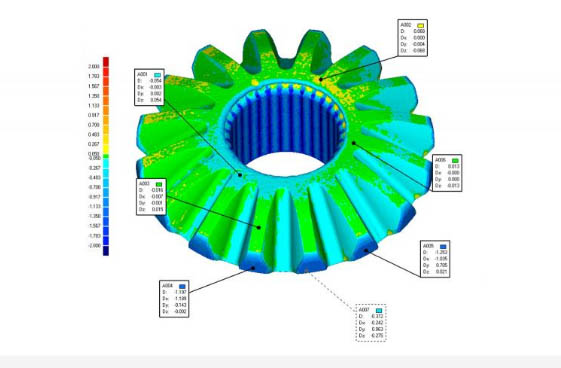
Once the gear is scanned, Intelgic's measurement software evaluates the configured checkpoints and generates a comprehensive quality report.
The report can include:
- Gear identification and inspection timestamp.
- Gear specification and selected measurement recipe.
- Actual measurements, nominal values, and tolerance limits.
- Tooth-by-tooth dimensional analysis.
- Helix and profile deviation graphs.
- Pitch and runout measurement results.
- 3D deviation maps highlighting out-of-tolerance regions.
- Detected surface defects and their locations.
- Overall inspection pass/fail result.
Example of a Digital Gear Quality Report
GEAR INSPECTION REPORT
Gear ID: GR-2048
Example data for illustration only
FAIL
# 40
Teeth scanned
# 7
Checks passed
# 1
Out of tolerance
| Parameter | Actual | Tolerance | Result |
|---|---|---|---|
| Outside diameter | 120.018 mm | 120 ± 0.05 | PASS |
| Root diameter | 107.992 mm | 108 ± 0.05 | PASS |
| Helix angle | 20.04° | 20 ± 0.10° | PASS |
| Tooth thickness | 4.012 mm | 4 ± 0.03 | PASS |
| Radial runout | 0.043 mm | ≤ 0.03 | FAIL |
| Total profile deviation | 0.014 mm | ≤ 0.02 | PASS |
| Total helix deviation | 0.017 mm | ≤ 0.02 | PASS |
| Tooth count | 40 | 40 | PASS |
Radial runout exceeds tolerance.
The gear is flagged for quality review.
These records can be exported and integrated with MES, ERP, or quality management systems to support part traceability and production analytics.
Applications Across Industries
Intelgic's 3D laser gear inspection solution can be configured for gears used in multiple industries.
| Industry | Applications |
|---|---|
| Automotive | Transmission gears, differential gears, gearbox components |
| Aerospace | Precision gears and actuator gear systems |
| Industrial Machinery | Spur gears, helical gears, machine tool gearboxes |
| Robotics | Precision transmission components and reduction gears |
| Heavy Equipment | Power transmission and drivetrain components |
| Energy | Wind turbine gearbox components and industrial power systems |
| Gear Manufacturing | In-process inspection and final quality control |
From Sampling Inspection to Automated Gear Quality Control
In conventional production environments, manufacturers often inspect selected gears from each batch using dedicated measurement equipment.
Intelgic's 3D laser inspection architecture is designed to support both standalone quality inspection cells and automated manufacturing lines.
The system can integrate with:
- Robotic loading and unloading.
- Motorized precision rotary stages.
- Rotary encoders and PLCs.
- Production conveyors and material handling.
- Barcode or QR code identification.
- MES, ERP, and quality reporting platforms.
For applications where cycle time and measurement uncertainty permit, this architecture can support 100% gear inspection rather than relying exclusively on sampling.
Measurement Accuracy and Validation
Precision gear metrology requires more than a high-resolution laser camera.
Actual system accuracy depends on sensor performance, calibration, rotary spindle accuracy, mounting eccentricity, optical access, surface reflectivity, and measurement algorithms.
Some features, especially steep tooth roots, hidden flanks, and internal geometries, may require additional sensor positions or complementary metrology. Laser gear measurement research identifies occlusion and reflective surfaces among the key technical challenges.
MDPI
For demanding applications, Intelgic can validate the measurement system against calibrated reference gears and established measurement methods. Requirements may be defined using relevant gear standards such as ISO 1328-1 and ISO/TR 10064-1.
Why Choose Intelgic for Automated Gear Inspection?
Intelgic combines industrial machine vision, 3D laser profiling, precision motion control, and intelligent measurement software to deliver application-specific gear inspection systems.
Our solution brings together:
- High-resolution 3D laser profile cameras.
- Precision rotary shaft and encoder synchronization.
- Sensor selection based on gear size and dimensional tolerance.
- Advanced 3D point-cloud reconstruction.
- Gear tooth segmentation and geometric measurement algorithms.
- AI-based surface defect identification.
- Automated tolerance evaluation and pass/fail decisions.
- Comprehensive digital gear quality reports.
- Integration with existing production and quality systems.
From small precision gears to large industrial components, Intelgic designs inspection solutions around the specific geometry and metrology requirements of each application.
Conclusion: Measure Every Critical Dimension with 3D Laser Gear Inspection
Gear quality depends on accurate geometry across every tooth, flank, and reference surface.
Manual inspection and conventional measurement approaches remain valuable, but modern gear manufacturing increasingly demands automated, repeatable, and digitally traceable quality inspection.
Intelgic's 3D laser-based gear inspection system combines precision rotational scanning, advanced geometric analysis, and AI-driven defect detection to automate gear quality assurance.
By measuring tooth thickness, helix angle, pitch, tooth depth, roundness, runout, profile deviations, and other critical checkpoints, the system helps manufacturers identify dimensional errors before defective gears move into assembly.
Every tooth. Every critical dimension. One comprehensive quality report.
Contact Intelgic to explore a customized 3D laser gear inspection solution for your manufacturing operation.
Frequently Asked Questions (FAQ)
1. What is 3D laser-based gear inspection?
It is a non-contact measurement process that uses laser profile cameras to capture three-dimensional gear geometry. Software analyzes the scanned data to calculate tooth dimensions, geometric deviations, and other quality parameters.
2. How does Intelgic's 3D laser gear inspection system work?
The gear rotates on a precision spindle while one or more 3D laser profilers capture its geometry. The system combines the scans into a 3D point cloud, extracts the required measurements, compares them with tolerances, and produces a quality report.
3. Can a 3D laser profiler measure gear helix angle?
Yes. With suitable tooth flank coverage and calibrated scanning geometry, the system can calculate helix angle, lead, and related tooth trace deviations.
4. Can it measure gear tooth thickness and depth?
Yes. Laser scanning can measure tooth thickness at defined reference locations, tooth tip and root geometry, addendum, dedendum, and total tooth depth.
5. Can the system measure roundness and gear runout?
Yes, provided the relevant surfaces are accessible and a suitable reference axis is established. The system can calculate roundness and radial or axial runout using the reconstructed geometry.
6. Can it measure pressure angle, module, and pitch circle diameter?
Yes. These parameters can be calculated or evaluated through measured geometry and the gear's design definition. The pitch circle is a theoretical reference, not a directly visible physical surface.
7. Does the system inspect every gear tooth?
It can be configured to inspect every accessible tooth during a complete rotation, rather than measuring only selected teeth. Actual coverage must be validated for the particular gear geometry.
8. Can the same system inspect spur and helical gears?
Yes. Different inspection recipes and appropriate scanner configurations can support both spur and helical gears.
9. What determines the selection of a 3D laser profiler?
Gear diameter, tooth size, face width, measurement tolerance, material, surface finish, scanning speed, and working distance determine the sensor configuration.
10. Can laser gear inspection detect chipped teeth and surface damage?
Yes. Geometric damage such as chipped teeth, burrs, nicks, and detectable surface irregularities can be identified from 3D scan data. Very fine cracks may require other inspection methods.
11. Can a 3D laser system replace conventional gear measuring machines?
It can automate many dimensional checks, but replacement depends on the required accuracy, uncertainty, accessible geometry, and relevant measurement standards. Some critical applications may still require dedicated tactile gear metrology.
12. Can Intelgic generate a complete gear inspection report?
Yes. The system can provide actual measurements, tolerances, tooth-level deviations, graphs, defect images or maps, pass/fail results, and digital inspection records.
13. Can the inspection system be integrated into a production line?
Yes. The system can integrate with rotary stages, robotic handling, PLCs, conveyors, MES, and factory quality management systems.
14. Can the system inspect large industrial gears?
Yes, subject to a suitable mechanical and optical configuration. Intelgic selects the laser profiler and motion architecture based on the gear's diameter, tooth geometry, and dimensional accuracy requirements.
15. How can manufacturers get started with Intelgic's gear inspection solution?
Manufacturers can share gear drawings or CAD models, gear dimensions, required checkpoints, tolerance limits, target inspection cycle time, and production volume. Intelgic can then evaluate the appropriate laser profiler and mechanical scanning configuration.