What Is AI-Powered Robotic Inspection? Fixed Cameras vs. Robot-Mounted Cameras
Modern products are becoming more complex, while manufacturers are expected to inspect more features without increasing production time. Components may have several surfaces, hidden joints, reflective finishes, complex geometries and small defects that cannot be observed from a single camera position.
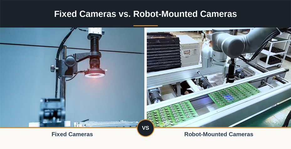
AI-powered robotic inspection combines industrial robots, machine vision and artificial intelligence to automate these demanding quality-control tasks. The robot presents a product to one or more cameras, or moves a camera around the product to collect images from carefully selected viewpoints. AI then analyzes those images to find defects, verify assembly and measure critical features.
Intelgic develops robotic inspection systems that bring together cameras, optics, lighting, robots, fixtures, AI software, controls and production integration as one engineered solution.
What Is AI-Powered Robotic Inspection?
AI-powered robotic inspection is an automated quality-control process in which a robot and vision system work together to inspect a product. The system may use:
- ◆2D industrial cameras
- ◆3D cameras or laser profilers
- ◆Line-scan cameras
- ◆Thermal cameras
- ◆Hyperspectral or specialized sensors
- ◆Controlled industrial lighting
- ◆Industrial or collaborative robots
- ◆AI defect-detection models
- ◆Conventional machine-vision tools
- ◆Measurement and reporting software
The robot provides programmable motion, while the imaging system provides visual information. AI interprets the images and distinguishes acceptable variation from genuine defects. Depending on the application, the system can:
- ◆Detect surface defects
- ◆Verify component presence
- ◆Check assembly completeness
- ◆Inspect products from multiple angles
- ◆Measure dimensions and gaps
- ◆Identify incorrect parts
- ◆Read text, barcodes and QR codes
- ◆Verify labels and markings
- ◆Detect contamination
- ◆Generate pass-or-fail decisions
- ◆Store images and inspection results
- ◆Guide sorting, rejection or rework
Intelgic’s robotic inspection approach is designed for products that are too large, complex or variable for a conventional single-camera inspection station. Intelgic robotic inspection systems
How Does a Robotic Inspection System Work?
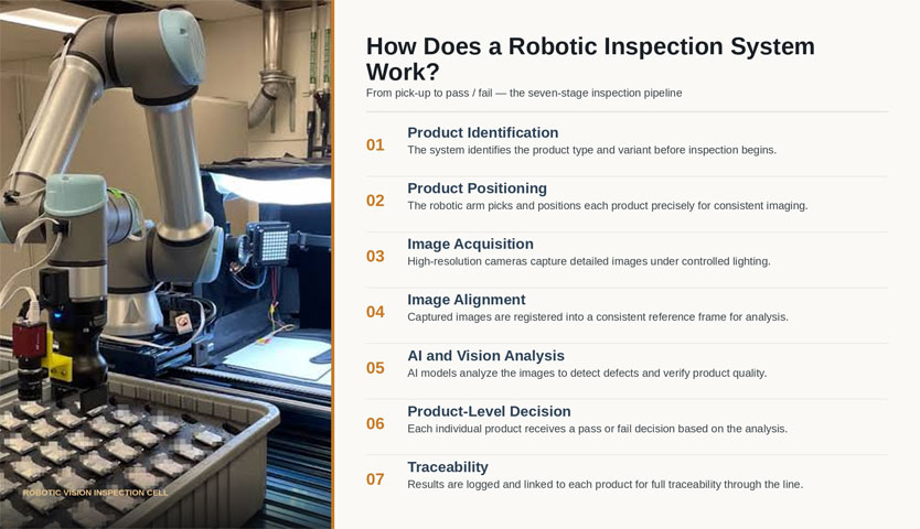
Although each application is different, a typical inspection cycle follows several stages.
1. Product identification
The system detects the arriving product and loads the correct inspection recipe. Identification may come from a barcode, RFID tag, PLC, manufacturing execution system or production schedule.
2. Product positioning
The product is placed on a conveyor, turntable, fixture or inspection table. Alternatively, a robot may pick up the part and present it to a stationary camera.
3. Image acquisition
The system captures images from the required viewpoints. The robot may move the part, move the camera or perform both actions in a coordinated sequence. At each inspection pose, the system controls:
- ◆Camera position
- ◆Camera-to-part distance
- ◆Viewing angle
- ◆Focus
- ◆Lighting direction
- ◆Exposure
- ◆Sensor settings
- ◆Robot settling time
4. Image alignment
Machine-vision software locates the product and aligns the image with the expected reference. This compensates for permitted changes in product placement and orientation.
5. AI and vision analysis
AI models detect irregular defects, while conventional tools perform defined measurements and logical checks. The system may inspect:
- ◆Cracks
- ◆Chips
- ◆Scratches
- ◆Dents
- ◆Corrosion
- ◆Porosity
- ◆Coating problems
- ◆Incorrect assembly
- ◆Missing fasteners
- ◆Weld defects
- ◆Sealant application
- ◆Connector position
- ◆Label or print errors
- ◆Dimensional nonconformity
6. Product-level decision
Results from every view are combined into a single pass, fail or review decision. A product can be rejected if one critical inspection fails or evaluated using a more detailed defect-scoring rule.
7. Traceability
Images, measurements, defect locations, product IDs and timestamps can be stored for audits, root-cause analysis and production improvement.
The Two Main Camera Configurations
The camera in a robotic inspection system can be installed in two principal ways:
- ◆Fixed in the inspection cell
- ◆Mounted on the robot
These arrangements are commonly called fixed-camera and robot-mounted-camera systems. In robotics terminology, they may also be described as eye-to-hand and eye-in-hand configurations. Neither approach is universally better. The correct choice depends on product geometry, inspection coverage, cycle time, accuracy, flexibility and cost.
Fixed-Camera Robotic Inspection
In a fixed-camera system, the camera is attached to a rigid frame, pedestal or enclosure. The robot moves the product into the camera’s field of view or reorients it to expose different surfaces. A fixed camera can also inspect a stationary product while a robot performs a separate operation.
How a Fixed-Camera System Works
The camera always observes approximately the same inspection region from the same position. The product may be:
- ◆Held by a robot
- ◆Rotated in front of the camera
- ◆Placed on a turntable
- ◆Presented on a conveyor
- ◆Located in a repeatable fixture
- ◆Moved between several fixed-camera stations
The robot can present different faces of the product to the same camera. Alternatively, several cameras can inspect multiple surfaces simultaneously.
Advantages of Fixed Cameras
Stable imaging geometry
Because the camera, lens and light remain stationary, the working distance and viewing angle are highly repeatable. This stability supports consistent image quality and precise measurement.
Faster image acquisition
Several fixed cameras can capture images simultaneously. A fixed camera may also acquire and process an image while the robot is moving or performing another task, which can reduce cycle time. Industrial robot documentation similarly notes that fixed cameras can support shorter cycles because image processing may occur while the robot performs other work. Fixed and robot-mounted camera comparison
Easier cable management
Power, data and lighting cables remain stationary. They are not repeatedly bent by robot motion, simplifying installation and reducing wear.
Controlled lighting
Lights can be mounted in a rigid, optimized geometry around the camera and product. This is valuable for reflective, glossy or highly textured surfaces.
Lower moving mass
The robot does not carry the camera, lens, light or protective housing. It can reserve more payload capacity for the product or tooling.
High repeatability
A rigid camera installation reduces variation caused by robot positioning. This can be advantageous for dimensional measurement and small-defect inspection.
Limitations of Fixed Cameras
Restricted viewing angles
A fixed camera can inspect only what is visible from its installed position. Hidden surfaces and deep features may require product manipulation or additional cameras.
More cameras for complex products
A product with many surfaces may need several cameras, lenses and lights. This can increase cell size, hardware cost and commissioning effort.
Possible occlusion
Robot tooling, fixtures or other product features may block the camera’s view.
Reduced flexibility
A camera arrangement designed for one product family may not provide suitable views for a significantly different product.
Best Applications for Fixed Cameras
Fixed cameras are often suitable when:
- ◆Products have a limited number of critical surfaces
- ◆Production speed is a major priority
- ◆The inspection pose is repeatable
- ◆Several cameras can capture views simultaneously
- ◆Precise and stable measurement is required
- ◆The robot can easily present the product
- ◆Part geometry does not create significant hidden regions
Typical applications include:
- ◆Small-component inspection
- ◆Assembly verification
- ◆Connector and pin inspection
- ◆Label and code verification
- ◆Fastener presence checks
- ◆Dimensional measurement
- ◆Product sorting
- ◆Inspection of robot-held parts
Robot-Mounted Camera Inspection
In a robot-mounted-camera system, the camera and often its light are attached to the robot wrist or end effector. The robot moves the imaging system around a stationary or fixtured product. This configuration is commonly called eye-in-hand inspection.
How a Robot-Mounted Camera Works
The robot follows a programmed path containing several inspection poses. At each pose, it stops or moves at a controlled speed while the camera captures an image or 3D scan. The same camera can inspect:
- ◆Top, side and bottom surfaces
- ◆Deep or recessed features
- ◆Large assemblies
- ◆Features at different heights
- ◆Areas requiring different viewing angles
- ◆Multiple product variants
By changing the robot program and inspection recipe, the system can accommodate new viewpoints without physically relocating several cameras.
Advantages of Robot-Mounted Cameras
Flexible viewing positions
The robot can move the camera to many positions and orientations. A single camera may replace several fixed cameras when inspections are sequential rather than simultaneous.
Access to difficult features
The camera can approach recessed, hidden or obstructed regions that a stationary camera cannot see.
Inspection of large products
A robot-mounted camera can travel around automotive assemblies, fabricated structures, appliances and other products that do not fit inside one field of view.
Adjustable camera distance
The robot can move closer for detailed inspection and farther away for a wider contextual image, provided the lens and focus arrangement support both positions.
Easier product changeover
New inspection positions can often be introduced through software and robot programming rather than major mechanical changes.
Consistent view of complex contours
The robot can orient the camera approximately normal to each inspected surface, improving visibility and reducing perspective distortion.
Limitations of Robot-Mounted Cameras
Longer cycle time
The robot must travel between inspection positions. Additional time may be required for the robot to settle before each image is captured.
Calibration complexity
The system must accurately establish the relationship between the camera and robot. This is known as hand-eye calibration. Hand-eye calibration converts camera observations into the robot’s coordinate system. It requires images and robot-position data from multiple, suitably distributed poses. Cognex hand-eye calibration guidance
Robot repeatability affects imaging
Changes in robot position can alter camera distance, perspective and lighting. The system design must account for the robot’s repeatability and the sensitivity of the inspection.
Cable and payload considerations
The camera, lens, light, housing and cables add payload to the wrist. Moving cables require appropriate robotic dress packs and strain relief.
Lighting is more difficult
A compact light may travel with the camera, but some defects need large diffuse or directional lights that are difficult to mount on a robot. Fixed lights can also be used, although their effectiveness may change with camera position.
Collision risk
The robot must approach the product without striking it, its fixture or surrounding equipment. Path planning, reach studies and safety design are essential.
Best Applications for Robot-Mounted Cameras
Robot-mounted cameras are often suitable when:
- ◆Products are large or geometrically complex
- ◆Many surfaces require inspection
- ◆Features are hidden or recessed
- ◆Product variants need different inspection paths
- ◆Cycle time allows sequential imaging
- ◆A single flexible sensor is preferable to many fixed cameras
- ◆The camera must maintain a particular angle to curved surfaces
Typical applications include:
- ◆Automotive body and component inspection
- ◆Weld inspection
- ◆Sealant and adhesive inspection
- ◆Casting and machining inspection
- ◆Battery-pack inspection
- ◆Aerospace structures
- ◆Large appliances
- ◆Complex assembled products
- ◆Surface inspection of molded components
Fixed vs. Robot-Mounted Cameras: Key Differences
| Decision factor | Fixed camera | Robot-mounted camera |
|---|---|---|
| Camera location | Attached to a stationary structure | Attached to the robot wrist or tool |
| Product movement | Robot or conveyor presents the product | Product may remain stationary |
| Number of viewpoints | Limited by physical camera positions | Many programmable viewpoints |
| Cycle time | Usually faster, especially with parallel capture | Includes travel and settling time |
| Imaging repeatability | Very high with rigid mounting | Influenced by robot repeatability |
| Complex geometry | May require multiple cameras | Strong access to complex surfaces |
| Lighting flexibility | Supports larger, rigid lighting arrangements | Limited by payload, space and motion |
| Product changeover | May require mechanical adjustment | Often handled through new robot poses |
| Calibration | Camera-to-cell or camera-to-robot calibration | Requires accurate hand-eye calibration |
| Cable management | Relatively simple | Requires moving cables or wrist-mounted processing |
| Hardware count | Can increase with each required view | One camera may cover several views |
| Best fit | Fast, repeatable inspections | Flexible, multi-angle inspection |
When Is a Hybrid System Better?
Many successful robotic inspection cells use both fixed and robot-mounted cameras. For example:
- ◆A fixed overhead camera identifies the product and estimates its position.
- ◆The robot-mounted camera inspects difficult surfaces.
- ◆Fixed side cameras capture several views simultaneously.
- ◆A robot moves a 3D sensor around the product for detailed measurement.
- ◆A fixed barcode camera verifies product identity before inspection.
- ◆A stationary backlight supports silhouette measurement while the robot presents the part.
A hybrid architecture can balance speed, flexibility and image quality. High-throughput inspections remain fixed, while only the features requiring special access are assigned to the robot-mounted camera.
2D, 3D and Specialized Sensors
Camera mounting is only one design decision. The inspection technology must also match the defect.
2D cameras
2D cameras are suitable for:
- ◆Surface appearance
- ◆Color
- ◆Texture
- ◆Print and labels
- ◆Component presence
- ◆Scratches and contamination
- ◆Barcode and OCR inspection
3D cameras and laser profilers
3D inspection is useful for:
- ◆Height and depth measurement
- ◆Dents
- ◆Gaps and flushness
- ◆Bead dimensions
- ◆Warpage
- ◆Missing material
- ◆Shape verification
- ◆Assembly geometry
Line-scan cameras
A robot can move a line-scan camera across a large surface, or move the product beneath a fixed line-scan camera. Consecutive image lines are combined into a high-resolution continuous image.
Thermal imaging
Thermal cameras can reveal temperature distribution associated with:
- ◆Electrical connections
- ◆Heat-sealing processes
- ◆Composite-material behavior
- ◆Insulation problems
- ◆Process variation
Multimodal inspection
Some defects require more than one sensor. Intelgic can combine 2D, 3D, thermal or other imaging modes and merge their results into one inspection record.
How AI Improves Robotic Inspection
Robotic motion provides access to the product, but AI determines what the captured images mean.
Supervised defect detection
AI is trained using labelled examples of known defects. It learns to locate and classify similar defects in production images.
Anomaly detection
When defective samples are rare, an anomaly-detection model learns the appearance of acceptable products and flags unusual regions.
Segmentation
Pixel-level segmentation identifies the shape and area of a defect. It can measure scratch length, coating loss, contamination area or damaged-edge size.
Classification
The system can categorize products or defects, such as:
- ◆Acceptable
- ◆Cosmetic defect
- ◆Functional defect
- ◆Rework required
- ◆Critical reject
Pose and feature recognition
AI can locate parts, identify product variants and help determine which inspection recipe or robot path should be used.
AI Does Not Replace Good Imaging
AI cannot reliably inspect a defect that the camera cannot see. Successful robotic inspection requires:
- ◆Adequate image resolution
- ◆Correct lens selection
- ◆Stable lighting
- ◆Suitable camera angles
- ◆Accurate robot motion
- ◆Repeatable product presentation
- ◆Representative training data
- ◆Clearly defined acceptance criteria
The imaging system must make the defect visible and separable from acceptable product variation. AI then improves the system’s ability to recognize and classify that defect.
Calibration: Connecting the Camera and Robot
Calibration creates a mathematical relationship between the camera, robot, product and cell coordinate systems. For fixed cameras, calibration allows the system to translate an image position into a robot-referenced position. For robot-mounted cameras, hand-eye calibration determines the camera’s position and orientation relative to the robot wrist. The resulting transformation enables images captured at different robot poses to be interpreted consistently. Calibration quality can be affected by:
- ◆Calibration-target quality
- ◆Number and distribution of calibration poses
- ◆Robot repeatability
- ◆Lens distortion
- ◆Camera mounting rigidity
- ◆Tool changes
- ◆Mechanical impacts
- ◆Temperature-related movement
Calibration should be verified during commissioning and checked periodically according to application risk and measurement requirements.
Designing the Robotic Inspection Cycle
A technically capable system must also meet production throughput. Cycle-time optimization may include:
- ◆Capturing images while the robot is moving, when image quality permits
- ◆Grouping nearby inspection poses
- ◆Using fixed cameras for simultaneous views
- ◆Moving the product instead of the camera
- ◆Optimizing robot acceleration and path
- ◆Running AI inference while the robot travels
- ◆Using multiple robots for very large products
- ◆Inspecting only product-specific critical regions
- ◆Separating rapid screening from detailed secondary inspection
The best architecture is the one that achieves the required inspection coverage within the available production cycle—not simply the one with the greatest number of camera positions.
How Intelgic Develops a Robotic Inspection System
Intelgic’s engineering process begins with the product and defect requirements.
Application study
The team evaluates:
- ◆Product dimensions and weight
- ◆Surface materials
- ◆Known defect types
- ◆Minimum defect size
- ◆Critical inspection regions
- ◆Product variants
- ◆Cycle time
- ◆Handling requirements
- ◆Existing automation
- ◆Traceability needs
Imaging feasibility
Representative acceptable and defective samples are tested using suitable cameras, lenses and lighting geometries.
Architecture selection
Intelgic determines whether the application is best served by:
- ◆Fixed cameras
- ◆A robot-mounted camera
- ◆A robot presenting the product
- ◆Multiple robots
- ◆A turntable
- ◆A hybrid inspection cell
AI development and validation
AI models are trained and validated using representative production data. Performance is assessed using practical metrics such as missed-defect rate, false-reject rate and defect-classification accuracy.
Robot and controls integration
The final system can integrate:
- ◆Industrial or collaborative robots
- ◆PLCs
- ◆Safety controls
- ◆Conveyors
- ◆Fixtures
- ◆Part-present sensors
- ◆Reject mechanisms
- ◆MES or manufacturing databases
- ◆Image and result storage
Applications of AI-Powered Robotic Inspection
Intelgic robotic inspection systems can support:
- ◆Automotive components and assemblies
- ◆Batteries and energy-storage systems
- ◆Electronics
- ◆Castings and machined parts
- ◆Welded structures
- ◆Aerospace components
- ◆Consumer products
- ◆Medical devices
- ◆Appliances
- ◆Plastics and molded parts
- ◆Packaging
- ◆Large fabricated products
- ◆Technical textiles and composite structures
Choosing Between Fixed and Robot-Mounted Cameras
A fixed-camera architecture is often the better starting point when the product is small, the required views are limited and cycle time is critical. A robot-mounted camera becomes attractive when the product is large, the geometry is complex or the system must inspect many features from different angles. A hybrid solution is often appropriate when some inspections demand maximum speed and repeatability while others require flexible access. The final choice should be based on a feasibility study rather than camera count alone. Inspection coverage, defect visibility, robot reach, lighting, calibration, throughput and future product variation must be evaluated together.
Frequently Asked Questions
What is AI-powered robotic inspection?
It is an automated quality-control process that combines robot motion, industrial imaging and AI. The robot moves the product or camera into suitable inspection positions, while AI analyzes the captured images for defects and assembly errors.
What is the difference between a fixed camera and a robot-mounted camera?
A fixed camera remains attached to the inspection cell while the product or robot moves within its field of view. A robot-mounted camera travels with the robot and can capture images from multiple programmable viewpoints.
Which configuration is faster?
Fixed cameras are generally faster when several images can be captured simultaneously or while the robot performs another task. Robot-mounted cameras require travel between viewpoints, although cycle time can be optimized through path planning and parallel image processing.
Can one robot-mounted camera replace several fixed cameras?
In some applications, yes. A robot-mounted camera can visit multiple inspection positions. However, replacing simultaneous fixed-camera capture with sequential robot motion may increase cycle time.
Which setup provides better measurement accuracy?
A rigidly mounted fixed camera generally provides more stable imaging geometry. A robot-mounted system can also achieve precise results, but its performance depends on robot repeatability, calibration, camera mounting and the measurement method.
What is hand-eye calibration?
Hand-eye calibration establishes the spatial relationship between a camera and robot. It enables the system to transform image coordinates into robot coordinates and interpret images captured at different robot positions.
Can the camera capture images while the robot is moving?
Yes, in suitable applications. The robot speed, exposure time, lighting and required resolution must be controlled to prevent motion blur and geometric error. Precision measurements may still require the robot to stop and settle.
Can a robot-mounted camera inspect inside holes or recessed areas?
It can inspect features that are optically accessible and within the robot’s reach. Deep, narrow or obstructed features may require specialized lenses, compact cameras, mirrors or alternative sensing methods.
Can AI detect defects it has never seen before?
Anomaly-detection models can flag regions that differ from learned acceptable products. However, production validation is still required to determine which defects are reliably detectable and to control false alarms.
Does robotic inspection require a six-axis robot?
Not always. The required motion may be provided by a six-axis robot, collaborative robot, gantry, linear stage, turntable or another programmable mechanism. The choice depends on product geometry, payload, reach, speed and safety requirements.
Can existing robots be used for inspection?
Potentially. Intelgic must evaluate robot payload, reach, repeatability, controller interfaces, available cycle time, cable routing and safety. Existing automation may limit the feasible camera positions or inspection speed.
Can fixed and robot-mounted cameras be used together?
Yes. A hybrid system can use fixed cameras for rapid, repeatable views and a robot-mounted camera for hidden or complex surfaces.
Is 3D vision always better than 2D vision?
No. 3D vision is valuable when height, depth or shape must be measured. 2D imaging may provide better resolution, color information or simpler detection for surface and appearance defects. Some applications benefit from both.
How accurate is AI robotic inspection?
Accuracy depends on defect visibility, imaging quality, training data, product variation and acceptance criteria. Performance should be validated on representative production samples using missed-defect and false-reject rates rather than a generic accuracy claim.
What information is needed for a feasibility study?
Useful information includes product drawings, dimensions, weight, material, production cycle time, inspection regions, minimum defect sizes, acceptable variation, existing robot details and representative good and defective samples.
Talk to an Intelgic Robotic Inspection Expert
Intelgic develops complete robotic inspection solutions using fixed cameras, robot-mounted cameras and hybrid architectures. Contact Intelgic to discuss your product geometry, defect requirements, production cycle and existing automation. Our team can evaluate the application and recommend the appropriate robot, imaging, lighting, AI and controls architecture.
Request a Demo