2D, 3D, Thermal and Ultrasonic Robotic Inspection Compared
Robots can carry many different inspection sensors, but those sensors do not reveal the same information.
A 2D camera records visible surface appearance. A 3D sensor measures shape and depth. A thermal camera detects patterns of infrared radiation associated with surface temperature. An ultrasonic probe sends sound waves into a material to evaluate internal conditions.
Selecting the wrong technology can produce an impressive inspection cell that cannot reliably see the target defect. Selecting the right sensor—or combining complementary sensors—allows robotic inspection to evaluate complex products consistently, safely and with full digital traceability.
Intelgic develops AI-powered robotic inspection systems using 2D vision, 3D measurement, thermal imaging and ultrasonic testing. The appropriate configuration is selected according to the material, defect location, inspection depth, product geometry, cycle time and applicable quality requirements.
What Is Multimodal Robotic Inspection?
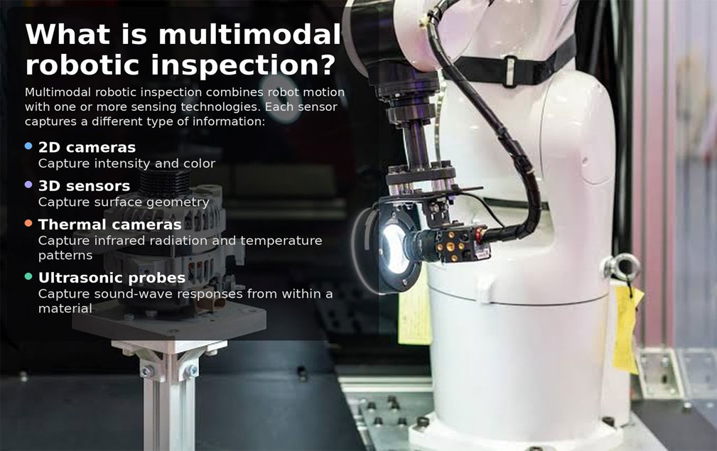
Multimodal robotic inspection combines robot motion with one or more sensing technologies. The robot moves a sensor around a stationary product, presents a product to fixed sensors or coordinates several sensors within one inspection cell. Each sensor captures a different type of information:
AI and analytical software process these datasets to identify defects, take measurements and produce a product-level decision. A multimodal system may combine, for example:
The robot gives these sensors flexible access to large, curved, multi-sided or difficult-to-reach products.
1. 2D Robotic Vision Inspection
A 2D camera captures a flat image composed of pixels. Each pixel represents brightness or color, but it does not directly provide height or depth. The camera may be fixed while a robot presents the product, or mounted on the robot to collect images from multiple angles.
What 2D vision can detect
2D robotic inspection is suitable for visible surface and assembly defects, including:
How it works
The system captures images under controlled lighting. AI models, image-processing algorithms or a combination of both analyze the appearance of each inspection region. The robot can position the camera normal to different surfaces, providing a clearer view of complex products than a single stationary camera.
Advantages of 2D inspection
Limitations of 2D inspection
A 2D image may not distinguish a color change from a height change. A dark region could be a stain, shadow, dent or acceptable material variation. 2D vision also cannot directly measure:
Its performance depends strongly on lighting. Reflective, transparent and dark materials may require several illumination angles or polarization.
Best applications
2D robotic vision is generally the first choice when defects are visible on the surface and can be distinguished by brightness, color, texture or shape.
2. 3D Robotic Inspection
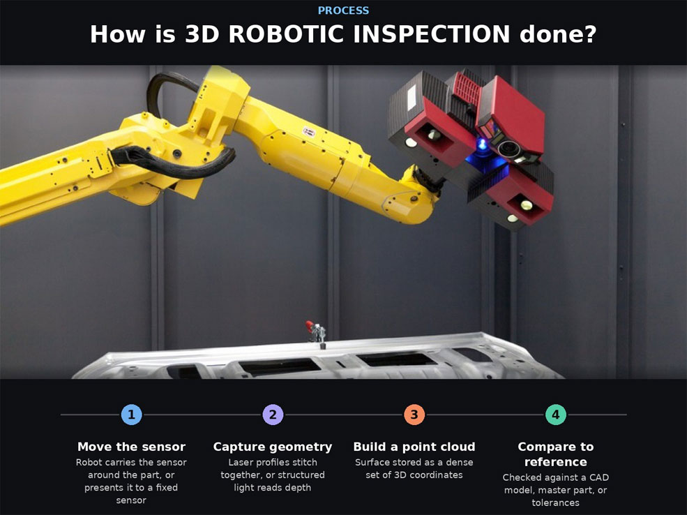
A 3D vision system measures the spatial shape of a product. Its output may be a depth map, height image, point cloud or 3D surface model. Common industrial 3D technologies include:
These technologies have different ranges, resolutions and surface requirements. ASTM has identified structured light, stereo, time-of-flight, LiDAR and related methods among the technologies relevant to industrial 3D vision selection. ASTM 3D vision technology work item
What 3D inspection can detect
3D robotic inspection is suitable for geometric defects such as:
How it works
The robot moves the 3D sensor around the product or presents the product to a fixed sensor. A laser profiler, for example, captures a cross-sectional profile. Movement of the robot or product combines consecutive profiles into a complete 3D surface. A structured-light camera projects a known pattern and calculates depth from its deformation. The captured point cloud can be compared with:
Advantages of 3D inspection
3D information is also valuable for identifying product position and orientation. NIST notes that 3D imaging provides the pose information needed for robotic tasks that would be difficult with conventional 2D sensing. NIST overview of 3D imaging for robotics
Limitations of 3D inspection
Best applications
3D is the better choice when acceptance depends on shape, height, depth, volume or spatial position rather than appearance alone.
3. Thermal Robotic Inspection
A thermal camera detects infrared radiation emitted and reflected by a surface. For calibrated radiometric systems, this information can be converted into an estimated surface temperature under defined conditions. The robot moves the camera around large equipment or positions it at repeatable angles and distances from each inspection region.
What thermal inspection can detect
Thermal robotic inspection can identify abnormal heat patterns associated with:
Passive and active thermography
Passive inspection observes temperature patterns already present during operation. Examples include:
Active inspection applies a controlled thermal stimulus, such as a flash, lamp, induction source or heating-and-cooling cycle. The camera observes how heat flows through the component. Defects such as delamination, voids or poor bonding may change the rate at which heat spreads or dissipates.
Advantages of thermal inspection
Limitations of thermal inspection
Thermal images do not directly show internal structure. They show surface infrared behavior influenced by:
Shiny metal can reflect infrared radiation from surrounding equipment or people, creating a misleading apparent temperature. Proper calibration, shielding, reference measurements and application-specific procedures are therefore essential. Thermal imaging may also fail to detect a defect that does not produce a measurable surface-temperature difference.
Best applications
Thermal inspection is appropriate when a defect changes heat generation, heat transfer or thermal response.
4. Ultrasonic Robotic Inspection
Ultrasonic testing sends high-frequency sound waves into a material. Reflections, transmission loss and travel time provide information about internal discontinuities and material thickness. Unlike 2D, 3D and thermal cameras, ultrasonic inspection normally requires the probe to remain at a controlled orientation and distance from the surface. Many methods also require a coupling medium such as water or gel.
What ultrasonic inspection can detect
Depending on the material, probe and test method, robotic ultrasonic inspection can detect:
High-frequency sound is commonly used in nondestructive testing to identify discontinuities inside components and structures. TWI robotic ultrasonic inspection overview
Ultrasonic inspection methods
A probe sends sound into the material and receives returning echoes. The time and amplitude of those echoes indicate material boundaries and possible defects.
One probe transmits sound from one side while another receives it on the opposite side. A reduction in transmitted energy may indicate a void, delamination or other discontinuity.
A probe containing several elements electronically controls the ultrasonic beam. It can inspect at multiple angles and create detailed cross-sectional data.
Air-coupled systems transmit ultrasound without liquid contact. They can be useful for composites, honeycomb structures and materials that should not be exposed to water, although signal and setup requirements differ from conventional contact testing.
Advantages of ultrasonic inspection
Robotic movement can maintain a defined scanning path, probe orientation and data spacing, reducing the variability of manual probe handling. ISO 24647:2023 specifies general hardware, component and acceptance requirements for robotic ultrasonic test systems using conventional probes and immersion techniques, with possible additional requirements for phased-array equipment. ISO 24647:2023
Limitations of ultrasonic inspection
Best applications
Ultrasound is appropriate when critical defects are inside a solid material or when wall thickness, bonding or weld integrity must be evaluated.
2D vs. 3D vs. Thermal vs. Ultrasonic Inspection
| Inspection factor | 2D vision | 3D vision | Thermal imaging | Ultrasonic testing |
|---|---|---|---|---|
| Primary information | Color and visible appearance | Surface geometry and depth | Infrared and temperature patterns | Internal acoustic response |
| Surface defects | Excellent | Good when geometry changes | Only when thermal behavior changes | Limited |
| Internal defects | No | No | Sometimes indirectly | Excellent for suitable materials |
| Color inspection | Excellent | Usually limited | No visible color | No |
| Dimensional measurement | 2D dimensions | 3D dimensions | Limited | Thickness and defect depth |
| Contact required | No | Usually no | No | Often yes |
| Couplant required | No | No | No | Often required |
| Inspection speed | High | Medium to high | Medium to high | Usually lower |
| Sensitivity to lighting | High | Technology-dependent | Not dependent on visible light | Not dependent on light |
| Sensitivity to surface finish | Optical reflections | Reflectivity and transparency | Emissivity and reflections | Coupling and surface condition |
| Typical robot use | Multi-angle imaging | Scanning and geometry capture | Repeatable thermal viewpoints | Controlled probe scanning |
| Best for | Appearance and assembly | Shape and deformation | Heat-related anomalies | Internal integrity |
Which Inspection Technology Should You Choose?
The choice should begin with the defect—not the sensor.
When One Sensor Is Not Enough
Many industrial defects require more than one sensing method.
This combination can distinguish discoloration from deformation. A dark area detected in 2D can be checked for corresponding depth in the 3D data. Applications include:
Visible imaging documents the component and its markings, while thermal imaging detects functional heat patterns. Applications include:
3D data creates the product’s surface geometry and helps generate a robot path. Ultrasound then inspects internal conditions while the robot maintains the required probe orientation. Applications include:
High-value or safety-critical components may justify a complete multimodal inspection cell. Each result can be registered to the same product coordinate system, producing a digital defect map containing surface appearance, geometry, thermal response and internal NDT data.
How the Robot Supports Each Sensor
The robot’s role changes with the inspection technology.
The robot selects viewpoints and maintains suitable camera distance and lighting angle.
The robot follows a controlled scanning path and provides position data for combining surface measurements.
The robot maintains repeatable distance, angle and observation time. For active thermography, its sequence may also be synchronized with a heating source.
The robot controls probe path, orientation, speed, contact force and data spacing. It may also manage a water-coupling nozzle or coordinate a second robot for through-transmission testing.
Calibration and Data Registration
A multimodal system must connect every sensor measurement with the correct physical location on the product. This may require:
Without accurate registration, a defect detected by one sensor may be assigned to the wrong product location or incorrectly compared with another dataset.
How AI Is Used Across the Four Technologies
AI is not limited to normal camera images.
For regulated or safety-critical NDT, AI output should be incorporated into a validated procedure with appropriate expert review. AI does not automatically replace qualified inspection personnel or applicable certification requirements.
Understanding Accuracy
No sensing method offers universal defect detection. Performance depends on:
Intelgic performs feasibility studies using representative products and defects. Performance is then validated using relevant metrics, such as:
Applications
Multimodal robotic inspection can support:
Intelgic’s Robotic Inspection Approach
Intelgic develops application-specific inspection systems that can include:
The system architecture is selected according to what must be detected—not according to a predetermined sensor preference.
Frequently Asked Questions
Expand each question to review the answer.
2D vision evaluates visible appearance, color and texture. 3D inspection measures surface height, depth and shape. A scratch may be easier to detect in 2D, while a dent is better measured in 3D.